
|
|||||||
| S40 / V40 '96-'04 General Forum for the Volvo S40 and V40 (Classic) Series from 1995-2004. |
 Information
|
|
CEM Wiring/Repair InformationViews : 219104 Replies : 357Users Viewing This Thread : |
 |
|
|
Thread Tools | Display Modes |
|
|
 Oct 25th, 2016, 17:11
|
#1 |
|
New Member
Last Online: Oct 25th, 2016 17:15
Join Date: Oct 2016
Location: Cookstown
|
Hello just wonder the year of your car mate? thank you Paul
|

|

|
|
Mar 10th, 2011, 21:04
|
#2 |
|
Winegrover
Last Online: Jul 17th, 2019 11:08
Join Date: Nov 2009
Location: Slovenska Bistrica
|
Well, it happen to one of our fellow volvo owner, who happens to know about electronics too. He soldered new relay in place and it worked. Later, he went to analyse the old relay part. He took it apart. Guess what he found - inside was another, smaller relay, soldered to pins of outer shell. How amazing is that ?!?!
|
|
|
|
| The Following 2 Users Say Thank You to sebaveh For This Useful Post: |
|
Jun 21st, 2011, 16:14
|
#3 |
|
New Member
Last Online: Jun 23rd, 2011 18:20
Join Date: Jun 2011
Location: Arvada
|
Hey, Russel,
thanks for the critical info. even with my background of 30 years in electrical, instrumentation, and electronics, it was really difficult to troubleshoot a system whose engineers are information anal. i hope this doesn't break forum rules re language. i am new to forums. I have replaced engine and trans on my daughters 2000 s40, and have been appalled at the info access difficulties. Thanks again ps, re protocols, are the couple of capital letters I put in for emphasis considered bad form? also, is there a way to contribute $$ to forum support? It of course is much cheaper than Vadis subscription, or buying even more bogus Vadis copies! lol :-) |
|
|
|
|
Jun 21st, 2011, 16:48
|
#4 | |
|
New Member
Last Online: Jun 23rd, 2011 18:20
Join Date: Jun 2011
Location: Arvada
|
Quote:
would be glad to pay for info, I have scoured the fujitsu database with no replacement relays compatible. no prob if just a relay base, but modifying the volvo cem prob not good idea. have you found replacement from any source? |
|
|
|
|
|
Jun 21st, 2011, 23:50
|
#5 | |
|
Premier Member

Last Online: Nov 15th, 2022 21:34
Join Date: Apr 2010
Location: London / Essex
|
Quote:
__________________
Current car: 2002 S40 1.9D, 1992 240SE Nullius in Verba
|
|
|
|
|
| The Following 2 Users Say Thank You to gatos For This Useful Post: |
|
Jun 30th, 2011, 16:51
|
#6 |
|
New Member
Last Online: Jul 1st, 2011 12:08
Join Date: Jun 2011
Location: Nykøbing Falster
|
Hey
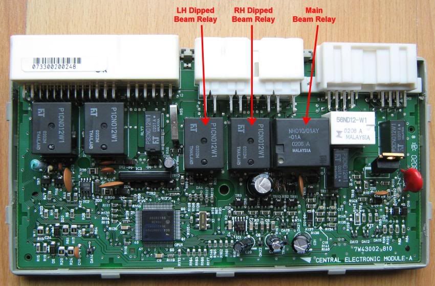
Does anyone have the schematic for the cem? or knows what component there is on place DA13 and DA12? Mine has fallen off.... and I have to replace the components.. Kim |
|
|
|
|
Jun 30th, 2011, 17:06
|
#7 |
|
Winegrover
Last Online: Jul 17th, 2019 11:08
Join Date: Nov 2009
Location: Slovenska Bistrica
|
My wild guess - it might be a double diode with common anode? Do you still have it lying inside housing?
|
|
|
|
|
Jun 30th, 2011, 17:10
|
#8 |
|
New Member
Last Online: Jul 1st, 2011 12:08
Join Date: Jun 2011
Location: Nykøbing Falster
|
Yes only the one. A little black thing in a SOD323 case... And I think that there is printet B3 on it.. I think it is the same as DA15. But I need more to ordre it from a anyone
Last edited by Kim4800; Jun 30th, 2011 at 17:14. |
|
|
|
|
Jun 30th, 2011, 17:18
|
#9 |
|
New Member
Last Online: Jul 1st, 2011 12:08
Join Date: Jun 2011
Location: Nykøbing Falster
|
A BZX399C2V2 from Philips ?
|
|
|
|
|
Feb 28th, 2015, 11:23
|
#10 |
|
New Member
Last Online: Mar 5th, 2016 09:43
Join Date: Jul 2013
Location: Treorchy
|
Hi All, I am a very new member of the forum and would like to thank you all especially Gatos and jordanfc for all the info on this subject, spent two days reading up and printing off the wiring diagram started working on the car yesterday 27/02/15, at 10 am, soldered in two relays, all fixed by 16.30.
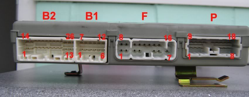
I have detailed the wiring diagram for high and low beams with the colour code but being a new member don't know how to put it on the site, To save time I also ran a wire from the Red lead connecting to the bulb (Disconnected from the bulb) outside the vehicle to the Drivers Footwell of the car and connected that to one of the probes on my multi meter and placed the other to the corresponding coloured wire to each of the headlight wires, that gave me a beep on my meter which told me that there was no break in the wire to that Headlight, also the same to the other side. I also checked for voltage input to the CEM by removing the centre connecter of the CEM tracing the necessary wire (Yellow / Red and Yellow White) which confirmed that I had voltage into the CEM, that in turn confirmed all of your theory, Once again thanks to all, you save me a fortune |
|
|
|
| The Following User Says Thank You to Commander For This Useful Post: |
|
| Currently Active Users Viewing This Thread: 1 (0 members and 1 guests) | |
|
|


 Hybrid Mode
