
|
|||||||
| 200 Series General Forum for the Volvo 240 and 260 cars |
 Information
|
|
240 speedo sender connector: does it just pull off?Views : 646 Replies : 5Users Viewing This Thread : |
 |
|
|
Thread Tools | Display Modes |
 Feb 22nd, 2022, 19:14
|
#1 |
|
New Member
Last Online: Feb 8th, 2024 14:01
Join Date: Dec 2009
Location: Market Drayton
|
Hello all, I have been thoroughly enjoying my "new" (1991) Torslanda estate bought just before the pandemic struck (phew!) It replaces the 1987 DL estate which is still sitting on the driveway in rather a sad state. The B200F injection engine gives actual acceleration, which the 2.3 DL lacked; the Torslanda is also much more economical, giving me 35 - 36 mpg, compared to 29 if I was lucky from the DL.
Anyway, the speedo and odometer suddenly stopped working the other day. Broken cable, I thought, until I did a bit of research online before crawling under the car. I was surprised to find the '91 Torslanda has an electronic speedo, which a quick look at the differential confirmed. (No car I have owned in my 46 years of driving has had an electronic speedo.) Nearly all the advice seemed to be that the speedo unit in the instrument cluster was likely to be at fault, but I wanted to check the easy stuff first. Under the car I went, then, and immediately saw the problem. One of the wires had broken just where it comes out of the sender unit; the other wire had lost an inch of insulation but was still intact. I jacked the car up a little to give myself a bit more room and tried to solder the broken wire back together. This was very difficult as there's an inch-and-a-bit diameter bar in the way, plus I'm trying to do this lying on my back. The biggest issue. though, was the fact that the solder just would not take. There was a lot of grease around, and the copper had corroded to an extent. The insulation just cracked off when I touched it. I managed to solder a length of new wire to the wire in the sheath (from the boot area) but without being able to connect it to the sender I am stuck. If I grasp the yellowish plastic in the sender unit with long nose pliers will it pull off? If so, I would be able to make up a new connector. Also, I wonder if all the grease around the unit has been applied by the former owner to protect things and make it easier to remove. It certainly doesn't look as dry as the differential in photos on the web. A little more background, which may or may not be relevant: the car was well loaded when the speedo stopped working. The wires connecting to the sender unit on the differential looked as if they had been strained, but there was on tension on them when I looked (after unloading the car). |

|

|
| The Following User Says Thank You to John Halford For This Useful Post: |
|
Feb 23rd, 2022, 09:29
|
#2 |
|
Senior Member
Last Online: Today 13:53
Join Date: Sep 2020
Location: Falkirk
|
The connector plug going into the diff should just pull off once you lift the clip on it. It should look like this under all the grime:
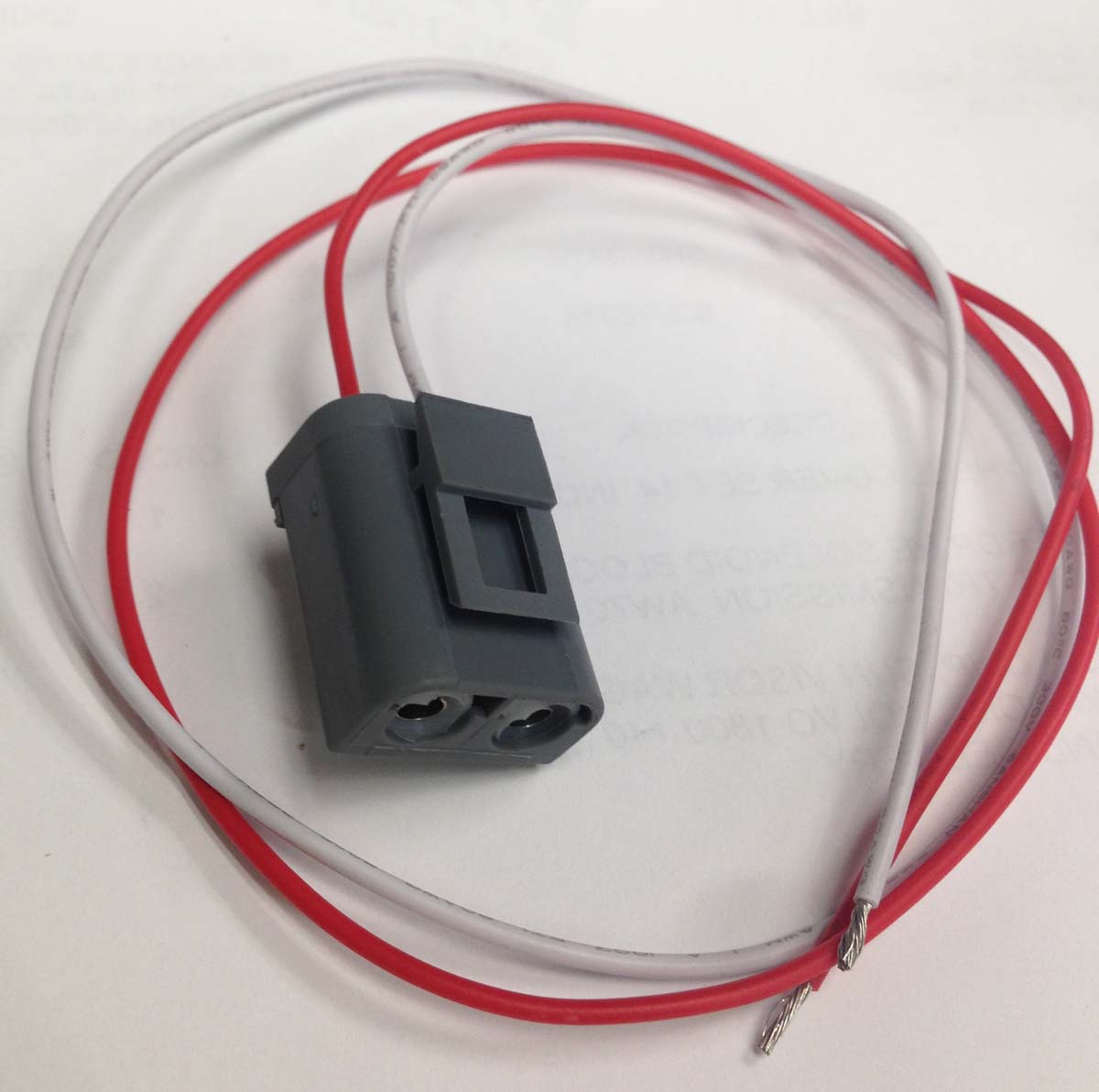 I'd recommend to first clear all the muck off it with degreaser or some strong washing up liquid and a brush, otherwise the solder won't stick. You should then be able to pull the whole connector off. It's probably best not to pull the individual crimped fittings out with pliers as they may not seat back in properly. The clip might break - that's alright, they're really brittle at this age. The plug will still keep itself attached with friction. If you're soldering the wiring back together, it might be worth adding a little bit of wire so it isn't so taut. Here you can see mine - the connector clip broke off. I snipped the wires and lengthened them using crimps and heatshrink.  Another alternative if the plug is completely shot, is to get some small female bullet connectors and use those to connect directly on to the pins on the back of the diff. If you get the right size, friction will hold them in place. This is what I had to do with my reverse light switch. |
|
|
|
| The Following User Says Thank You to Juular For This Useful Post: |
|
Feb 23rd, 2022, 09:55
|
#3 |
|
New Member
Last Online: Feb 8th, 2024 14:01
Join Date: Dec 2009
Location: Market Drayton
|
Thanks Juular. I'll attack it with a toothbrush and washing up liquid. I just wasn't sure what I was looking at, and I didn't want to break anything. So the wires I can see are coming out of the back of the black connector clip. I'll report back on progress later ...
|
|
|
|
| The Following User Says Thank You to John Halford For This Useful Post: |
|
Feb 23rd, 2022, 22:00
|
#4 |
|
New Member
Last Online: Feb 8th, 2024 14:01
Join Date: Dec 2009
Location: Market Drayton
|
Update: I have managed to remove the plug from the sender unit. One of the bullet connectors stayed attached to one of the pins but it came off easily with the help of pliers. Next I will clean it up a bit more, solder extra lengths of wire to the connectors and reinstall. I will attach some photos of the plug if I can work out how to do it. It took me a little while to realise that to release the plug you have to squeeze in the outer (wires) end of the clip. It's obvious now, when I look at the photo of the new plug above.
|
|
|
|
|
Feb 24th, 2022, 09:14
|
#5 |
|
Master Member
Last Online: Today 12:47
Join Date: Nov 2012
Location: London and Cambridge
|
Now youve removed the gray plastic connector case youll be able to see that it can be unclipped and opened to remove the two bullet connectors and wires from within it. Volvo used those gray connectors and the bullets within it in various places in the 240, in 2, 3 and 8 pole versions so if you have any spare wiring you may have some spare connectors already.
There are other locations no doubt, but: The indicator units use a 3 pole version Theres a 2 pole version near the coil The bulkhead connector is an 8 pole version Ive cut sections out of scrap cars to keep a few of these spare- they also fit perfectly on the gearbox reversing light switch. Cheers |
|
|
|
|
Feb 24th, 2022, 17:55
|
#6 |
|
New Member
Last Online: Feb 8th, 2024 14:01
Join Date: Dec 2009
Location: Market Drayton
|
Bugjam1999, thank you. I didn't know the plug could be opened up - I had already managed to solder bits of wire to the connectors.
So ... it's all reinstalled and reconnected. The plug just would not go all the way home, no matter how hard I pushed with a screwdriver on the end. The individual connectors seemed to be being forced out, so I left it at that. The photo might show what I mean. There was no way the clip was going to engage, so I hope it stays in situ. I took it for a quick road test - and it works (hooray!) I'm thinking I should smear all over with vaseline to try to prevent ingress of water. Good idea? |
|
|
|
|
| Tags |
| mpg, speedometer not working |
| Currently Active Users Viewing This Thread: 1 (0 members and 1 guests) | |
|
|


 Linear Mode

