

|
|||||||
| S40 / V40 '96-'04 General Forum for the Volvo S40 and V40 (Classic) Series from 1995-2004. |
 Information
|
|
Cylinder Head Transplant B4204S EngineViews : 15653 Replies : 21Users Viewing This Thread : |
 |
|
|
Thread Tools | Display Modes |
|
|
#1 |
|
VOC Member
Last Online: Apr 4th, 2023 18:13
Join Date: Apr 2010
Location: Oxford
|
My Christmas present to you is the inevitable guide arising out of my experiences documented in this thread:
Introduction and disclaimers There's little here that isn't in Haynes or in the Vida instructions that a kindly member (such as gatos or 960kg) can doubtless provide, if you can't find them using a forum search. I consulted the Vida instructions for the T4 engine (B4194T2) that gatos had already helpfully posted in post #49 of this thread. (It's not the same engine, but it's similar enough for these purposes.) I am no mechanic. Most people undertaking this job will know far more than I do, and they won't need this guide. This was by far the biggest job of its kind that I had ever undertaken – indeed my previous experience was limited to very basic servicing – changing spark plugs, oil, and coolant. My aim is not really to add any wisdom that can't be found elsewhere, and certainly not to claim any expertise; but merely to try to make the job less daunting for the inexperienced and fearful – people like me, in other words – by providing some pictures and a single linear set of instructions – and by advertising the fact that even someone with as little experience as I had was able to manage it... I found that Haynes makes you jump around between sections, which makes it rather hard to follow. It also irritates me that Haynes never tells you the head-size of the bolts and things that you are trying to remove, and leaves you peering at and feeling for things with a series of different sockets or spanners in turn, before you find the one that fits; so I have tried to provide this info in most cases (but the information here still isn't comprehensive). But I would definitely recommend that you read Haynes (and Vida if you can get access to it) alongside this guide. And do use the forum for guidance when you are unsure – there are plenty of extraordinarily knowledgeable and helpful members to help you if you are unsure about anything. I did this job because I had a burned exhaust valve – and I simply replaced the old head with one from a scrapped car, which was very kindly removed for me by gatos. Some would say that it was foolhardy of me to proceed without having the replacement head checked for flatness and pressure-tested. I'm not here to tell you how to make judgement calls like that. But obviously, if you are doing it because of a blown head gasket, you will need to take appropriate steps to check for and, if necessary, remedy any distortion. I did the job without a camshaft locking tool – and in this one respect my guide does differ from the instructions in Haynes and Vida. In advance of tackling the job, I found myself in quite a lot of doubt and fear about whether I needed one or not, and guidance seems to vary. I think it's important to make clear that, and how, one can very comfortably manage without. Whereas I had believed in advance that the hardest thing about the job would be getting the timing right, the reality was that that part was pretty straightforward. The only thing that makes the job at all hard is the very limited access at the side of the engine. Note, label, and photograph as you go along. You will end up with an alarming number of bits that you have removed, and unless you are very fast at completing the job you are likely soon to forget what is what. I used food bags with post-its inside to keep track of things. And keeping these bags in the order of removal of parts made it fairly easy to keep track of what I had to do when it came to putting it back together. What you need - Spanners and sockets, mostly of ordinary dimensions (10mm to 18mm covers it I think), but also including a 30mm socket/spanner for the crankshaft nut (which takes a lot of undoing as it is very tight). - Screwdrivers flat- and cross-headed, and torx drivers T30 and T40. - 2mm hex tool for the coils. - A long bar to turn the two things that need a lot of leverage (the cylinder head bolts and the crankshaft nut). I have a two-foot breaker bar that did the job. - A tool that you will have to make yourself to hold the crankshaft pulley still so that you can undo its central nut. I managed to make this myself, which proves that just about anyone can do it. It consists of two strips of steel about half a centimetre thick and about eighteen inches to two feet long. Drill 8mm holes in both ends of each, and use a nut and bolt to fix them them together at one end.  - Torque wrench(es) covering 10 Nm to 180 Nm - New cylinder head gasket - New inlet and exhaust manifold gaskets - New stretch bolts for the cylinder head x10 - New timing belt - Volvo chemical gasket for the camshaft cover and a small roller to roll it on with - Some would say you should get new camshaft oil seals. The advice I had from the mechanics at my tame Volvo specialist is that if they are not already leaking or damaged you can get away with re-using the old ones; which is what I did. Preliminaries 1. Disconnect the negative lead from the battery. 2. Remove the plastic cover from the top of the engine if you have one. 3. Drain the coolant. The safest way (least likelihood of damaging anything) is to undo the lower radiator hose clip (the troublesome thing documented in this thread that you ought to replace with a stainless steel one, if you haven't done it already.) 4. Loosen the hose clips on the top radiator hose at the top of the radiator and by the thermostat housing. Remove the hose. 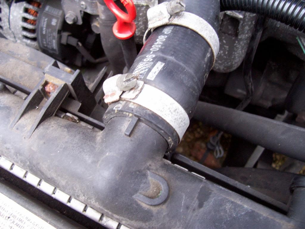 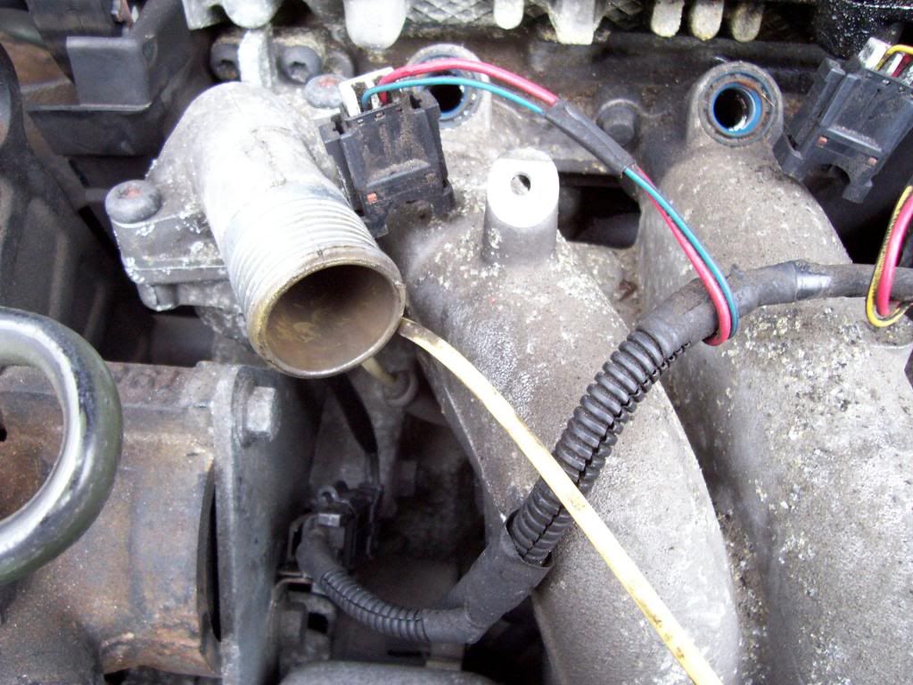 5. Undo the connector to the engine coolant temperature sensor that is screwed into the thermostat housing. I made it my policy to label every such connector that I came across, by sellotaping a bit of paper inscribed with some suitable abbreviation (e.g. 'ECT' in this case) to the wiring next to it. Auxiliary belt 6. Remove the metal guard over the power steering pulley on the auxiliaries belt. A 10mm bolt. A bit fiddly to get at, but nothing compared with what is to come. 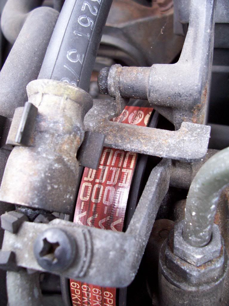 7. Jack up and safely support the front right-hand side of the car; remove the right-hand road wheel and free the inner part of the wheel arch liner (two 13mm bolts). Haynes seems to suggest that you can pull this liner out; I never managed that; it seemed to be held on by some hidden fixing of insuperable strength in a place that I couldn't see... but it's not important, so long as you can fold it back to gain access to the side of the engine. 8. Get a 15mm spanner on the auxiliary belt tensioner pulley and turn it clockwise till the tensioner can be locked in the belt-untensioned position. To lock it, use a drill bit pushed through the holes that will line up more or less directly above the oil filter when you have turned it far enough. 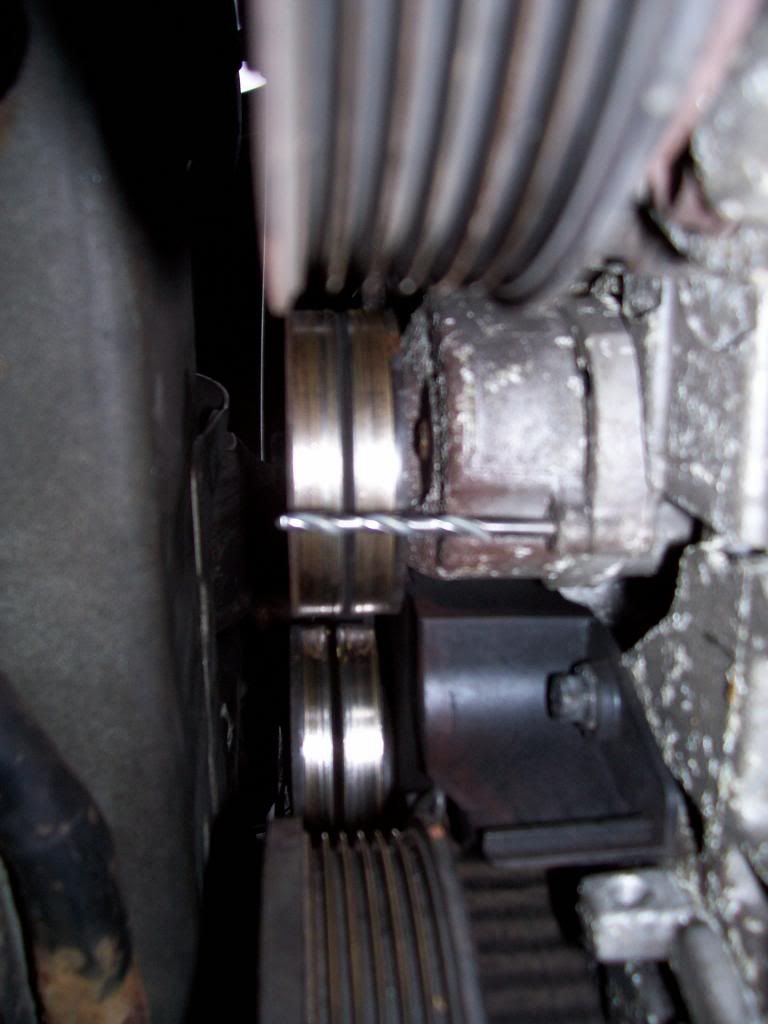 It takes a fair bit of force to turn it enough – or anyway mine did. If you are working alone, and you find that you can't get enough purchase and/or don't have enough strength to turn it, you could do what I did and hook a ring spanner over the pulley, with the handle hanging down into the wheel arch; and then use a jack gradually to lower the free end of the spanner on to an axle stand or similar, so that the weight of the car is providing the turning force. (Presumably this technique comes with the risk that things will slip and that the spanner will fly off at high speed and go through your head or something. You have been warned  ) If I were doing it again I would buy a new 15mm spanner, longer and with a more suitable offset than the one that I was using, so that I could pull the tensioner pulley clockwise from above. And/or I would get someone to help me. ) If I were doing it again I would buy a new 15mm spanner, longer and with a more suitable offset than the one that I was using, so that I could pull the tensioner pulley clockwise from above. And/or I would get someone to help me. 9. Remove the auxiliary belt. Timing belt (preliminary) 10. Remove the timing belt's outer cover. This is held on by a 12mm bolt rather inconveniently positioned down the side of the engine and buried in a recess in the plastic of the timing belt cover, as you can see better here with the cover removed. 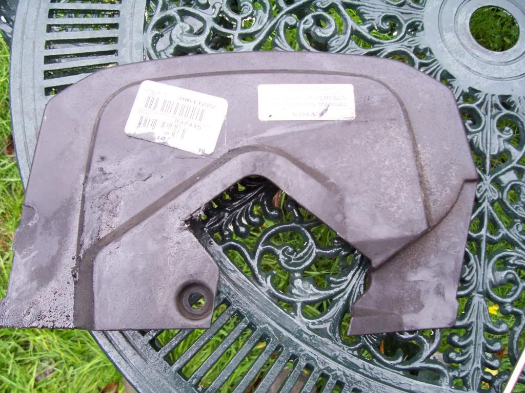 The only way that I could see to get at it was to move the power steering reservoir by undoing its two 10mm bolts. There is no need to disconnect the pipes to/from the reservoir – you just need to be able to move the reservoir itself a few inches, so that you can get a normal socket on to the bolt that you are trying to remove. 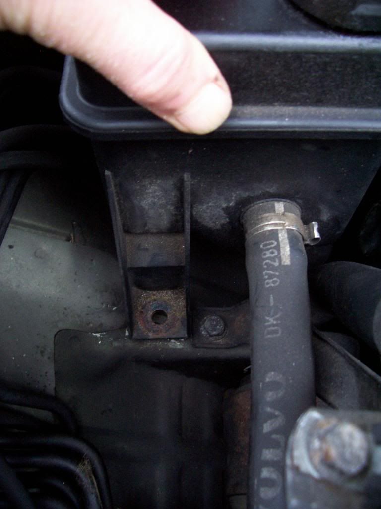 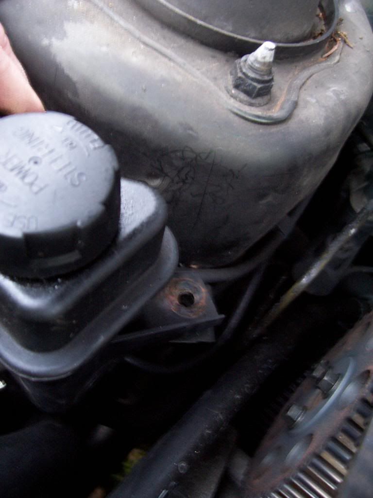 11. Get your 30mm socket/spanner and rotate the crankshaft centre nut until the two timing marks on the camshaft sprockets are aligned with the marks in the timing belt top cover. The timing marks are just tiny lines – one engraved in each of the sprockets, and two plastic protuberances on the edge of the timing belt top cover. You can see them (roughly) aligned here: 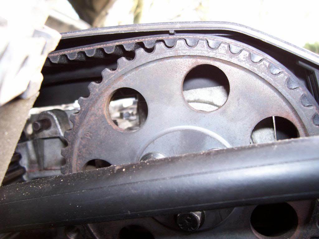 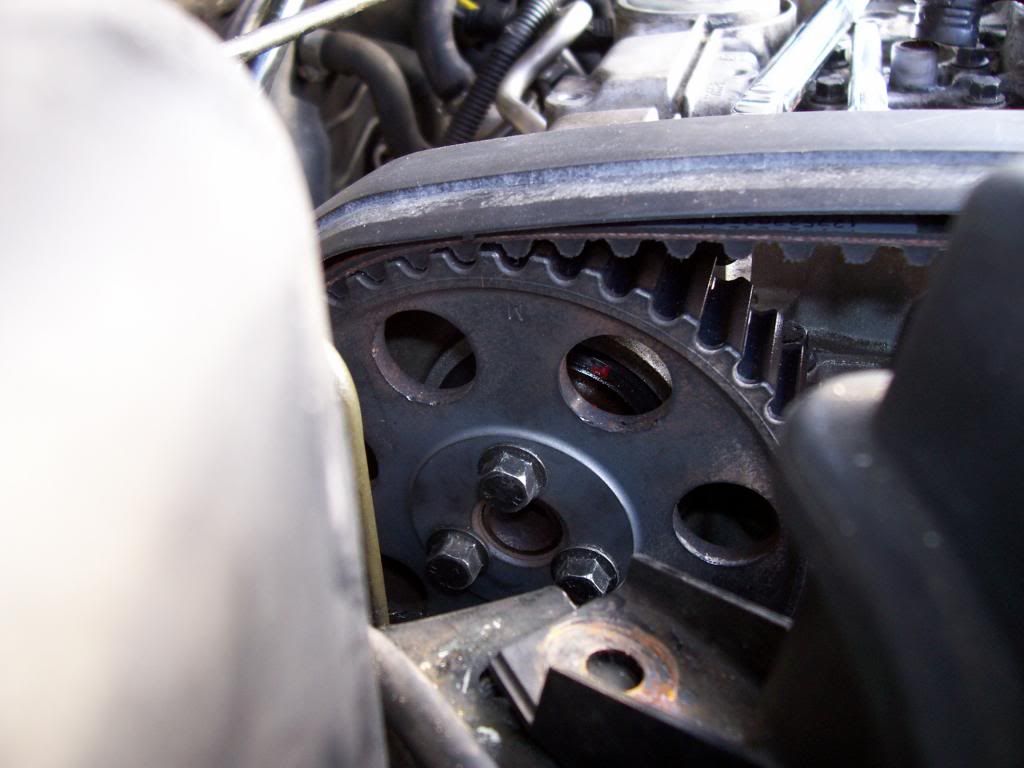 This puts the camshafts in the position you want them to be in when you rebuild. These positions are not critical at this stage, as you can adjust things later before fitting the new timing belt; but it is arguably helpful to have things in roughly the right place for later on. 12. Remove the timing belt top cover (two 10mm bolts). Electrical/ignition stuff 13. There's a large metal bracket that sits on top of the engine and holds the ignition coils and so on. Everything needs to come off this, so that it can be removed. So... 14. Pull the ignition leads off the spark plugs. 15. Remove the ignition coils from the bracket. Three 2mm hex-headed screws hold each one on. Remember that the one on the left, as you look from the front of the car, is for cylinders 2 and 3 (leads have a grey connector). The one on the right is for cylinders 1 and 4 (leads have a black connector). 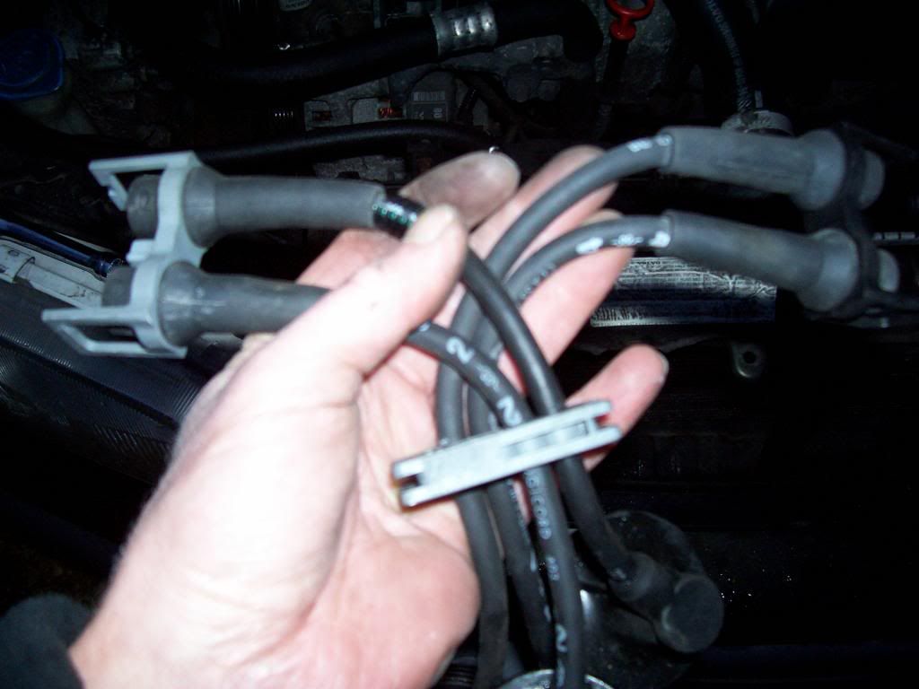 16. Undo the earth strap (a 10mm bolt) from the wiring that goes to the coils. 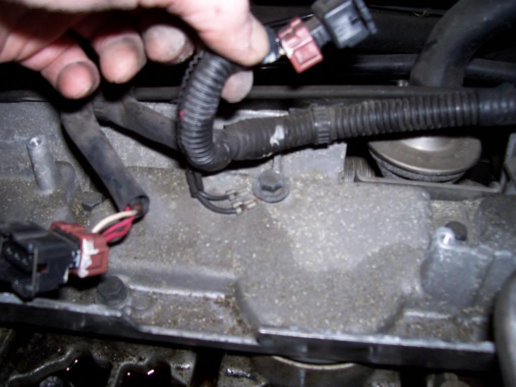 17. There are two plastic clips that hold the wiring that supplies the coils to the metal bracket that you are clearing of stuff. Ease the clips through the holes in the bracket to release them. 18. There is a rigid metal pipe that snakes out of the top of the cam cover and round the back of it. You have to remove the two obvious screws on top, and two well-hidden T30 screws behind the rear edge of the bracket, to free it. 19. You can then access all of the 10mm bolts that hold the metal bracket on, and remove it. Air and fuel stuff 20. Haynes tells you to remove the complete air intake system, including the air box. That's much more work than is really necessary. All you really need to do is disconnect all the stuff that would otherwise prevent you from removing the inlet manifold. If you simply disconnect it all from the engine, you can gently park all of this stuff to the side, and you will have plenty of room to work, and to get the old head out and the new one in. So... 21. Remove the plastic cover that sits above the throttle (a single Phillips screw). 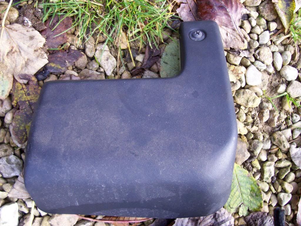 22. Disconnect the crankcase ventilation hose from the main air intake duct – the big fat black pipe that goes from the airbox to the throttle housing. It fits tightly but just needs to be pulled strongly. 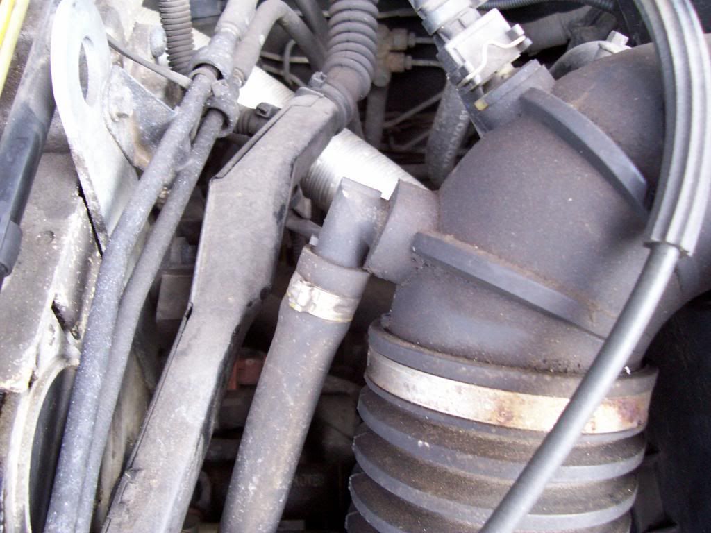 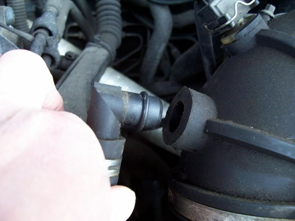 23. Disconnect the similar breather hose from closer to the throttle. It has a bayonet fitting – turn it about 30 degrees anti-clockwise and you can pull it out. 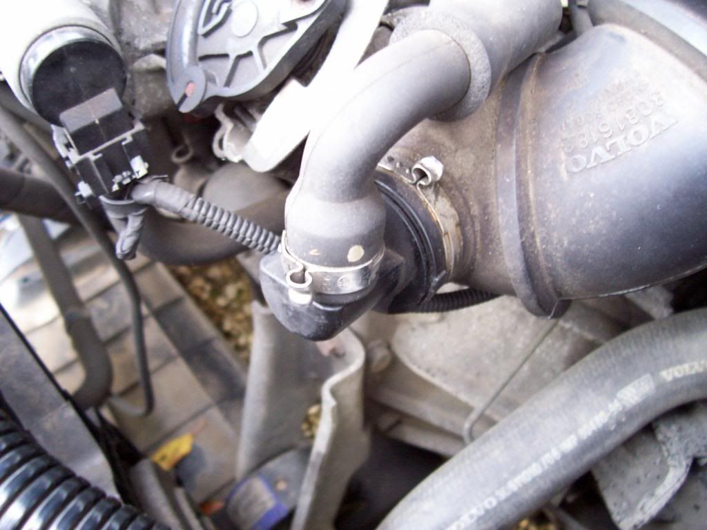 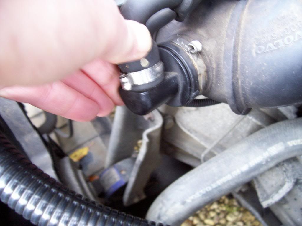 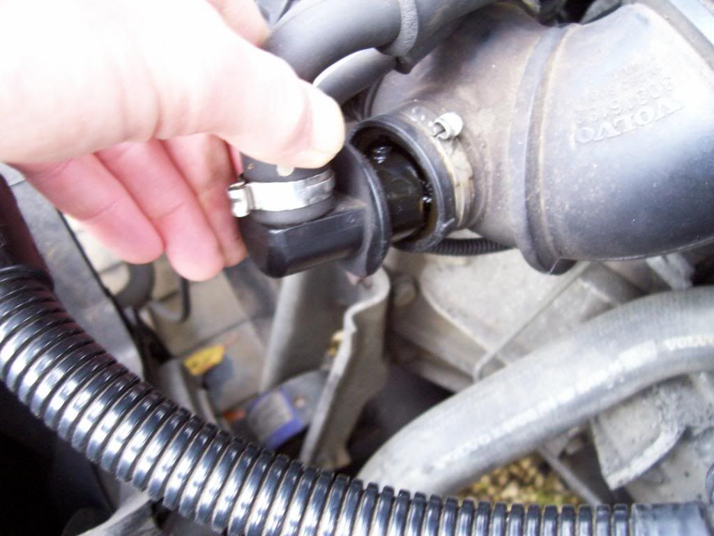 24. Pull off the vacuum hoses from the inlet manifold beside the throttle body. Take a photo or three before you do it so that you can see how they go back on. (Though, as my elder son said, “How much can it matter? Can't you just put them back any way they seem to fit?” … which is in fact probably right, though he couldn't have known it...) 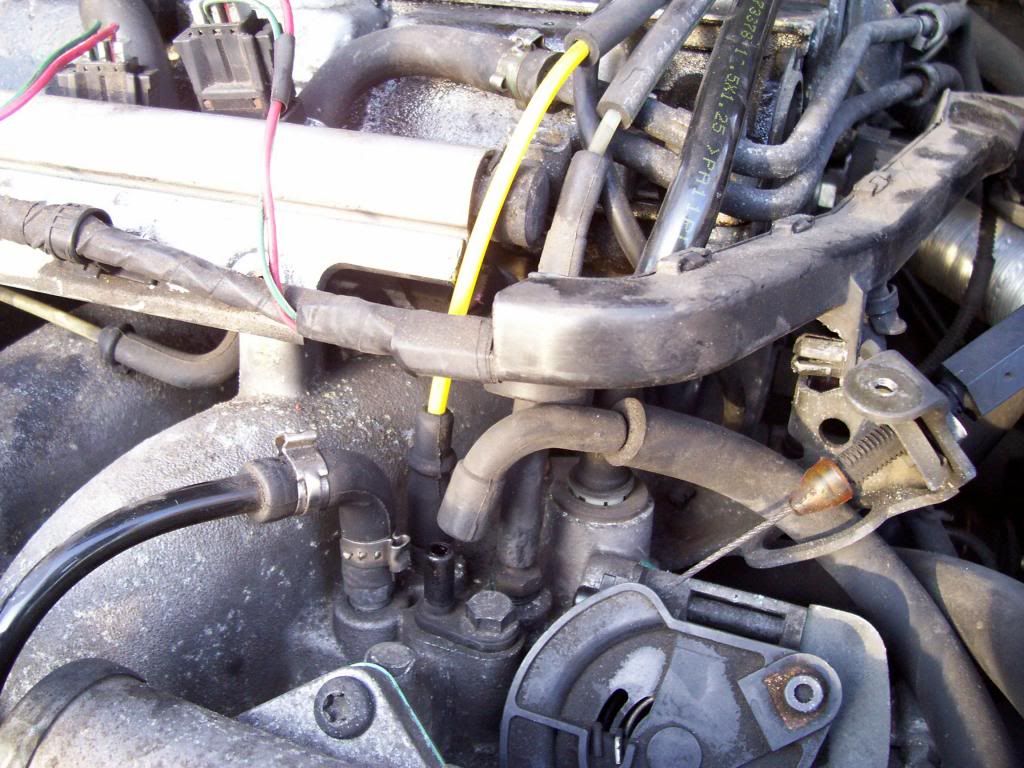 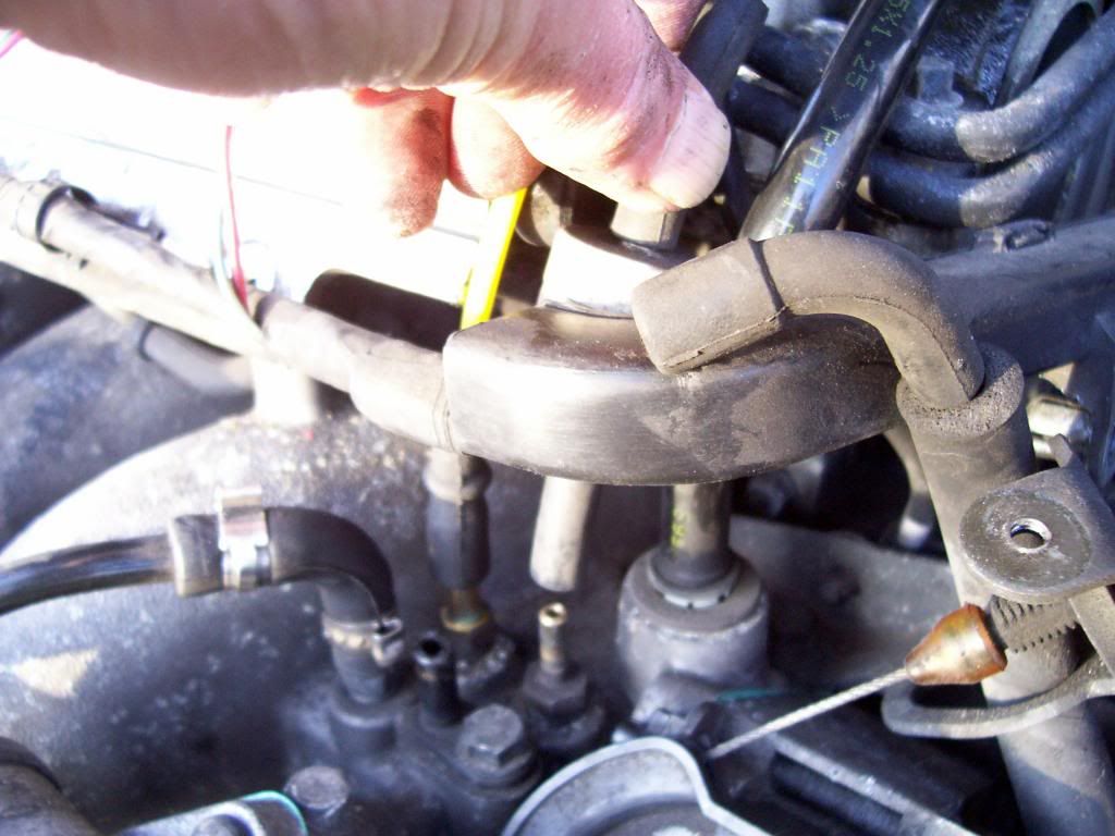 To remove the shiny black vacuum hose that goes to the brake servo, you need to hold down the top edge of the white collar that is in the manifold with a thumbnail or the end of a screwdriver, while pulling up on the hose itself. 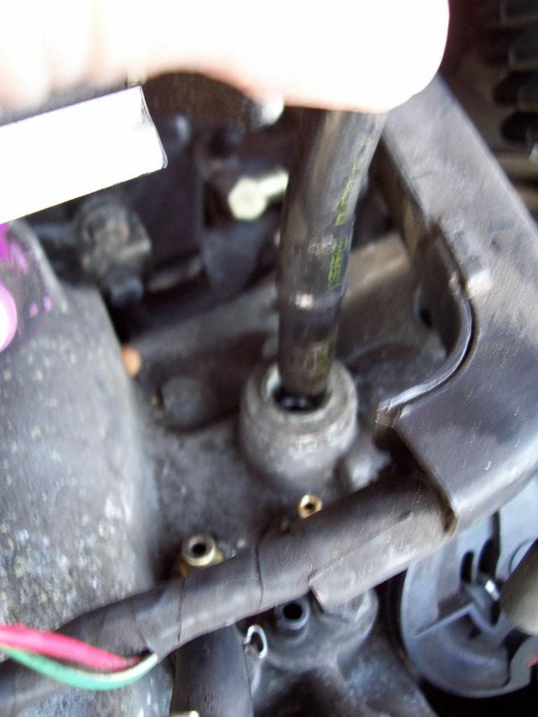 One of my vacuum hoses here had a little metal hose clip that had to be released first. The other ones you can just carefully pull/twist/wiggle off. 25. Use a screwdriver to loosen the large hose clip on the main air intake duct at the throttle housing, and pull it off the throttle housing. 26. Detach the wiring connector from each of the four fuel injectors just above the fuel rail. 27. Depressurise the fuel rail by unscrewing the plastic dust cap at the left-hand (as you look at things from the front of the car) and depressing the little metal pin in the centre of the valve inside (it's a valve that looks just like an ordinary tyre valve). A bit of fuel will squirt out, so have a rag ready to catch it. Screw the cap back on so that you don't lose it. 28. Undo and remove the small (10mm) nut and bolt that hold the fuel pipes to the large lifting bracket on the inboard side of the engine, near the centre of the engine bay. This will allow you to swing the fuel rail and fuel pipes away from the engine without having to disconnect the fiddly fuel pipe connections. 29. The wiring to the injectors is held by a rigid plastic wiring-duct that comes down the inboard side of the cylinder head. There is a larger nut that holds this rigid plastic ducting to the side of the head, just below the nut for the fuel pipes that you just undid. Remove this nut, so as to free up the wiring a bit. 30. Unbolt the fuel rail from the inlet manifold and pull it carefully away from the manifold. The injectors will either come away with the rail, or will be left behind in the manifold. Either way is fine. Just carefully gather up any of the little O-rings that may come off either end of the injectors, or of the little round rubber seals that are behind the injectors on the fuel rail – one or two of mine made a bid for freedom at this point. 31. Remove the injectors and put them away somewhere safe. It's important not to bash them around. 32. Pull off the vacuum hose to the fuel pressure regulator that is attached to the fuel rail. 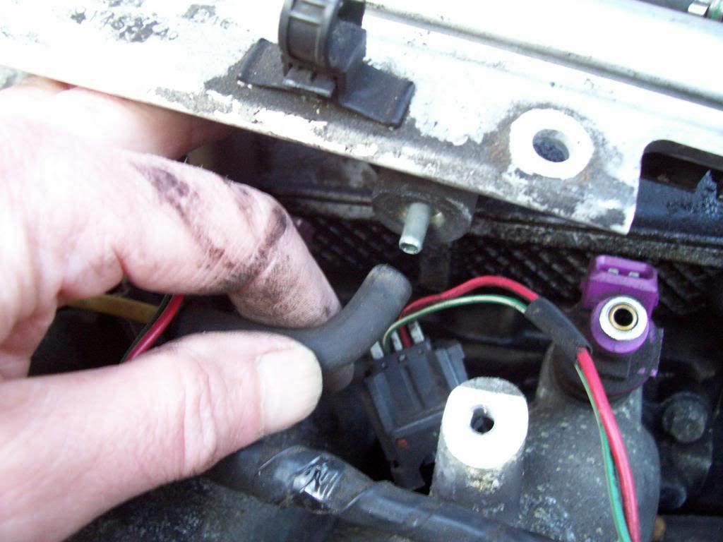 33. Carefully swing the fuel rail and the pipes leading to it up and out of the way over to the right-hand side (as you look at it from the front of the car) of the engine bay – over with the air intake stuff. Throttle and manifolds 34. Detach the throttle cable from the metal bracket that curves up from the rear of the right-hand end of the inlet manifold. The cable is fastened by a little metal horseshoe-shaped clip underneath; pull this off and you can slip the cable off the bracket. 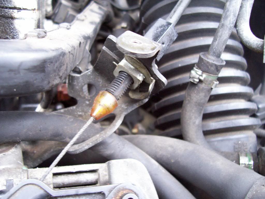 35. Remove the bracket from the manifold (two bolts). 36. Disconnect the throttle position sensor's wiring connector from under the throttle body. 37. Unbolt the throttle body. It has four 10mm bolts. Remove it and stow it carefully somewhere over near the battery where it is out of the way. (There's no need to detach the throttle cable from the throttle body.) 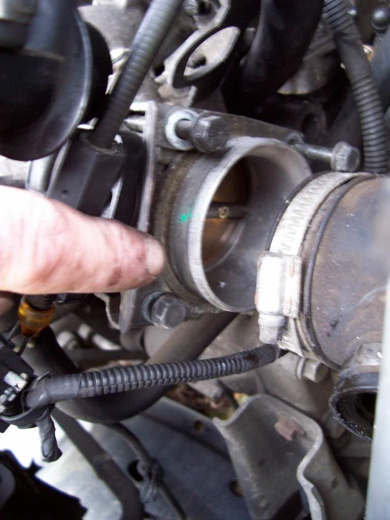 38. Disconnect the wiring connector from the idle control valve. 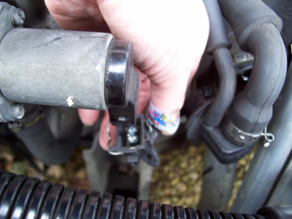 39. Remove the idle control valve (two torx bolts). 40. Get bits of paper and sellotape and use them to label the wires close to the two connectors that you just undid. Do the same for the FPR vacuum pipe that was attached to the underside of the fuel rail. 41. Undo the 12mm bolt that goes up from below and holds the manifold to the support bracket that is below it. 42. Undo the 10mm bolt that holds the oil dipstick to the inlet manifold. 43. Undo the bolt that holds a further hose and the starter motor's wiring to the front of the manifold. 44. Undo another bolt on the front of the manifold – the one in the middle of the picture below, immediately to the left of the air con pipe and below the rivet that you can see. 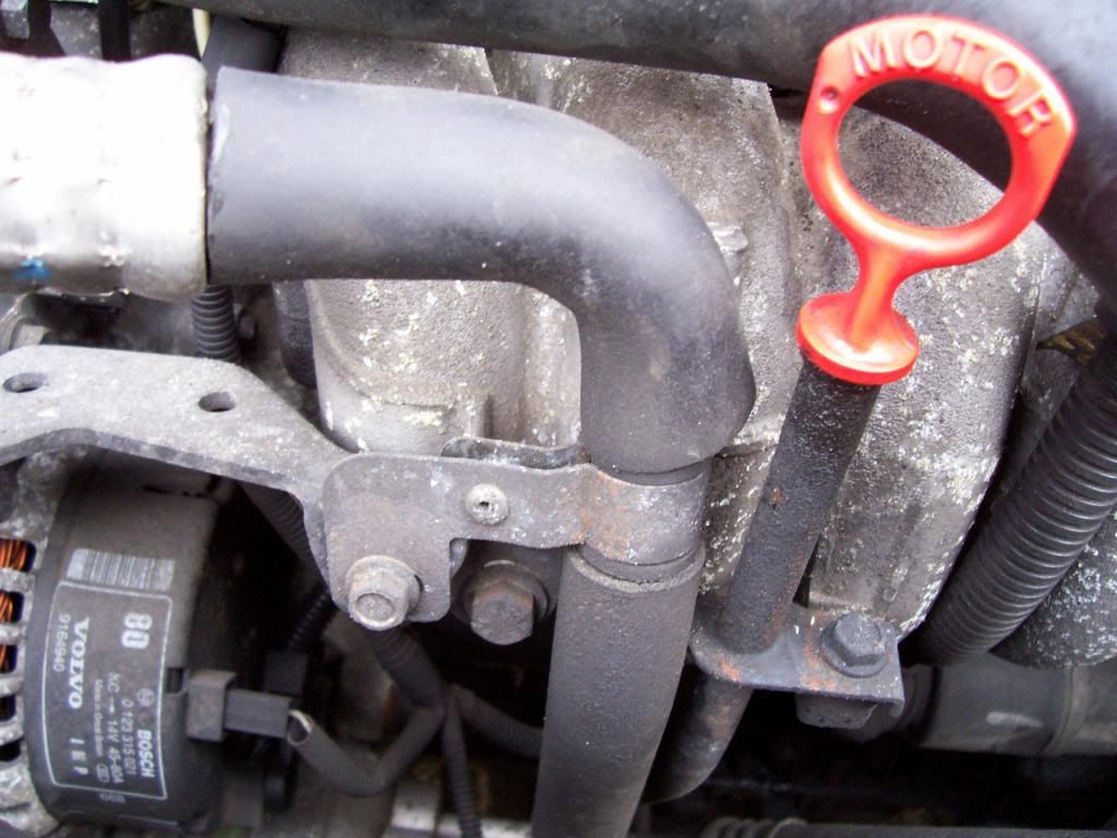 45. Undo the metal clip securing the black crankcase ventilation hose (the one that snakes up through the inlet manifold) to the top of the cam cover. 46. Remove the inlet manifold. It is held on by six 10mm bolts – three on top and three underneath. The lower ones only need to be loosened, as the manifold has slots – rather than holes – on the lower edge, so that if you remove the upper bolts and loosen the lower ones you can lift it up and away from the cylinder head, easing the free end of the crankcase ventilation hose through the manifold as you go. 47. There is a flexible metal hose running from the heat shield over the exhaust manifold to the airbox. Pull it off the tubes at each end. 48. Undo the heat shield behind the exhaust manifold. There are two bolts with springs on the top edge, that screw into the rear top edge of the cylinder head, and two smaller ones that go directly into the rear of the manifold. Lift the heat shield out. 49. Spray Plus Gas on the exhaust manifold nuts. Ideally, do this well in advance of trying to remove the manifold, and ideally do it repeatedly over a period of a few days, especially if yours look badly rusted. 50. Release the manifold from the downpipe by undoing the two 13mm nuts with springs that attach to the threaded prongs that come down from the exhaust manifold. Best access to these nuts is from below the car. 51. Undo the exhaust manifold from the head. Eight nuts that go on to studs that should remain in the head. Remove the manifold and the four gaskets. 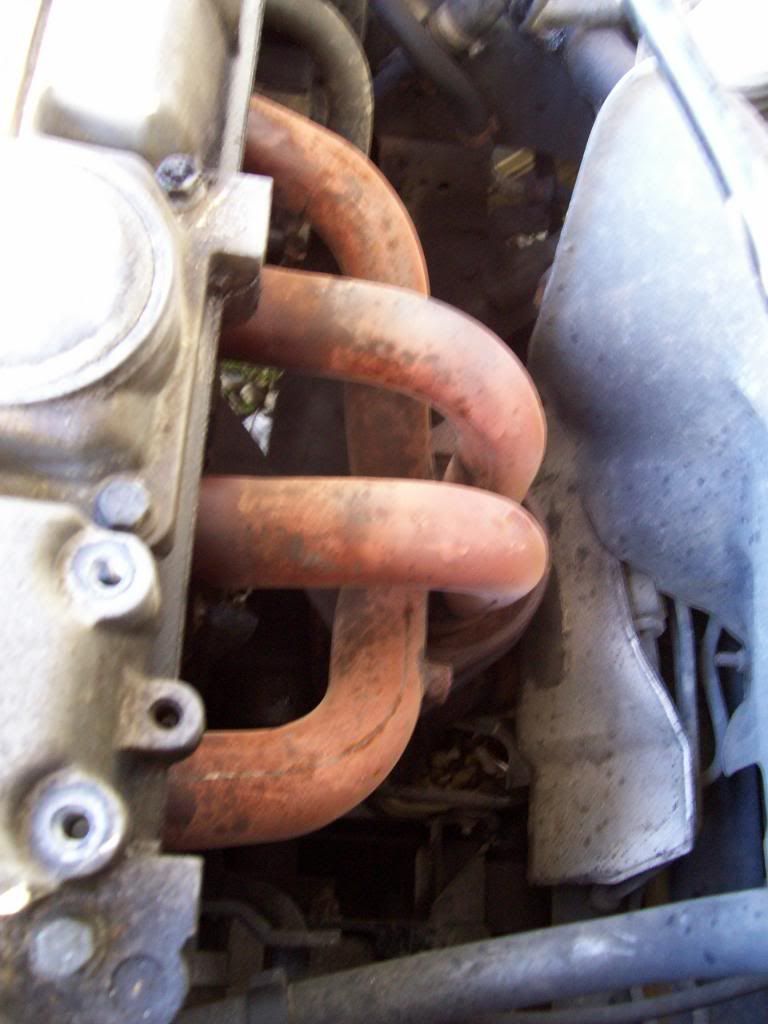 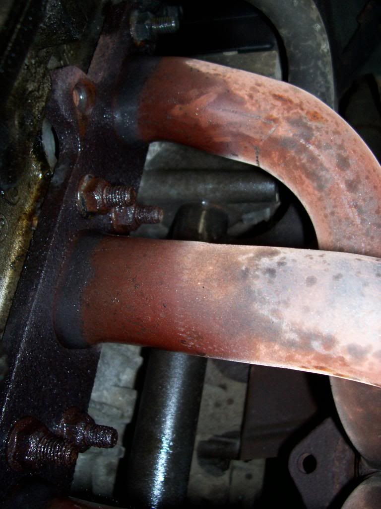 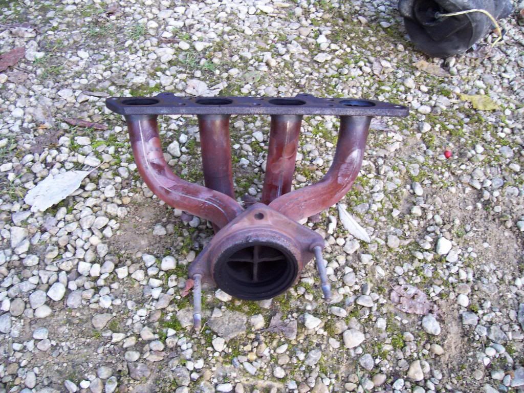 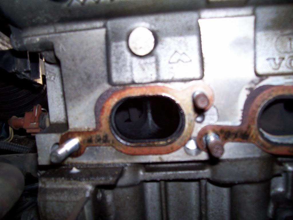 Camshafts etc 52. Use paint to mark the positions of the camshaft sprockets on the camshafts. Remember that your paint marks can be as big as you like, as you are ultimately going to be lining up the edges of the marks for accuracy. The crucial thing is that they should have distinct edges, and that the paint should overlap the join between sprocket and camshaft in a way that will enable you to restore the alignment exactly. Here are my own splodges, which served me well enough: 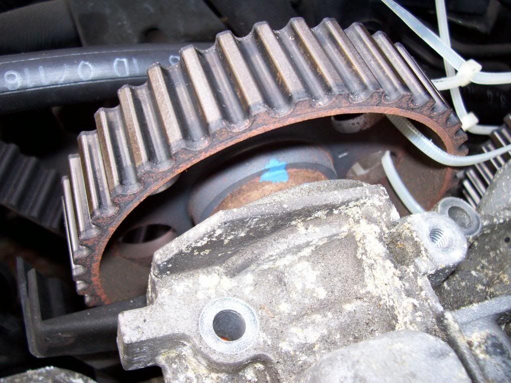 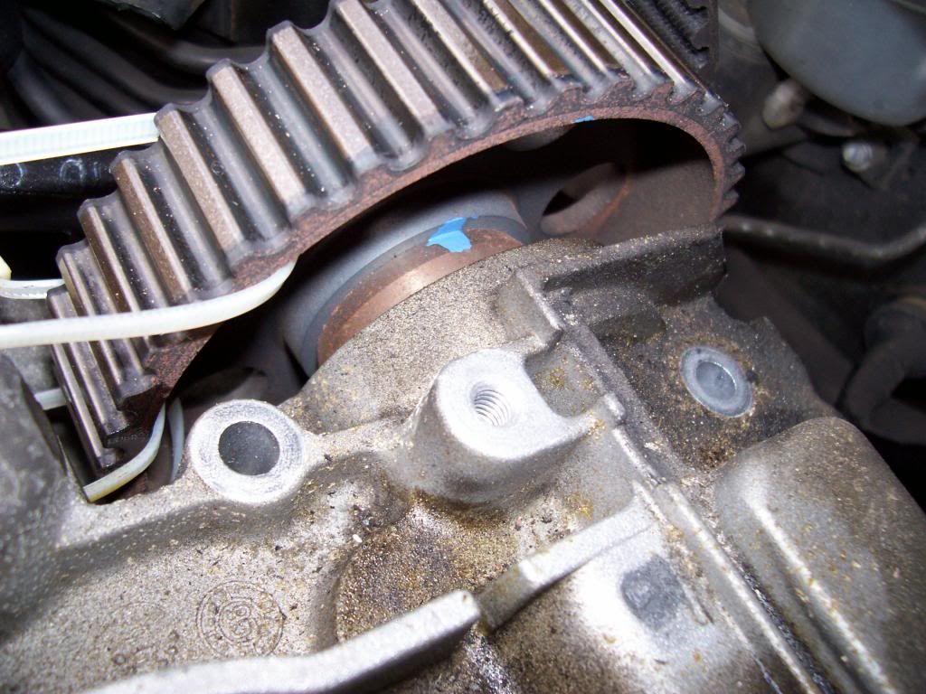 (Ignore the cable ties on the sprockets in these pictures. At this stage I was merely trying out another member's technique of using cable ties to lock the positions of the camshafts for the purposes of a timing belt change. I just wanted to see how firmly they held them.) 53. Remove the timing belt. I simply cut mine with a sharp knife, as all the good advice says that you are going to buy a new one rather than try to re-use the old one. You can worry about pulling it off the lower pulleys and sprockets later on. 54. Undo and remove the camshaft sprockets (three 10mm bolts on each one). Mark the sprockets so as to indicate which is which. I did a single blob of paint for the inlet sprocket, and a pair of triangular splodges for the exhaust sprocket. 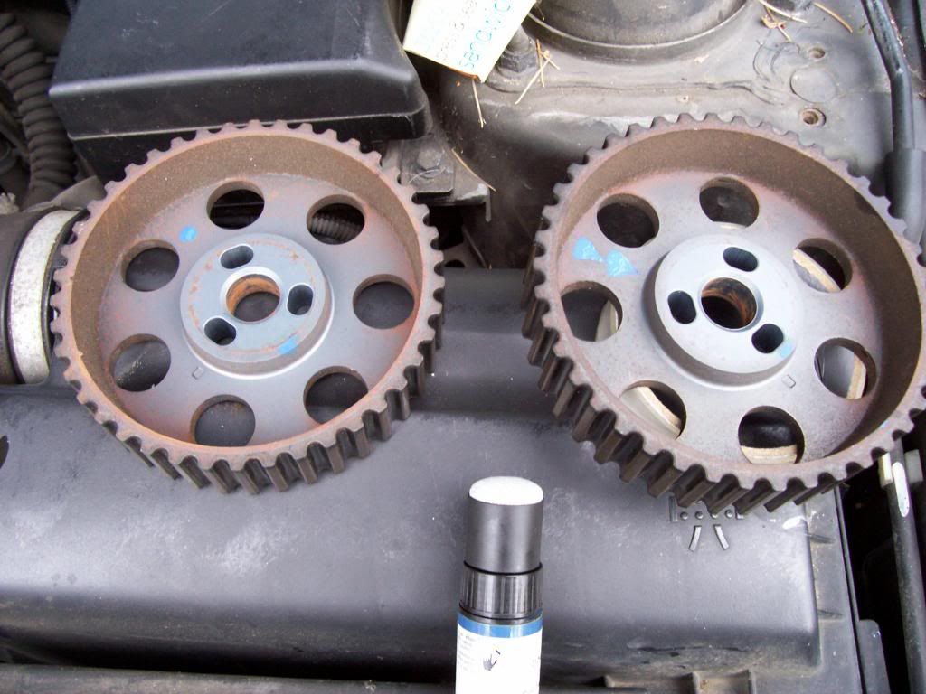 55. Undo the cover for the camshaft position sensor – two T30 torx bolts. 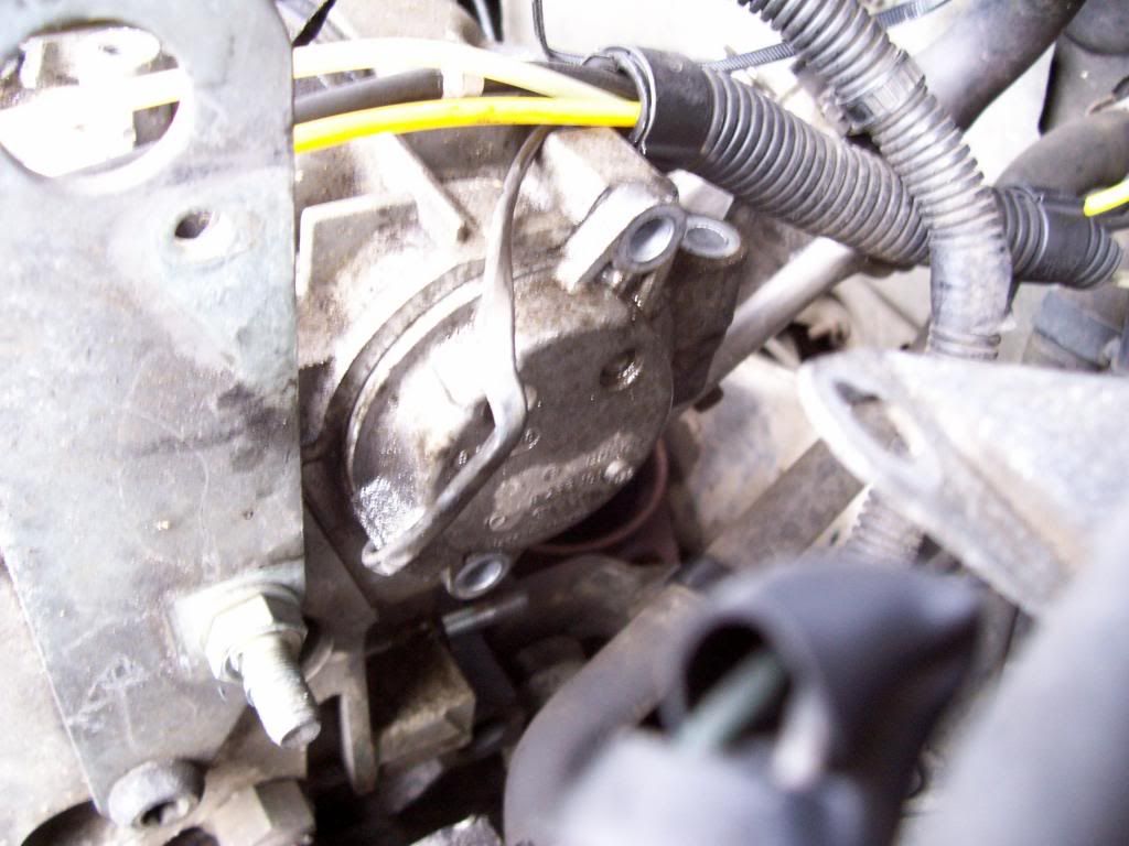 56. Under the cover is the rotor itself whose rotations the sensor detects. It is held on by a single 10mm bolt; undo it and remove. 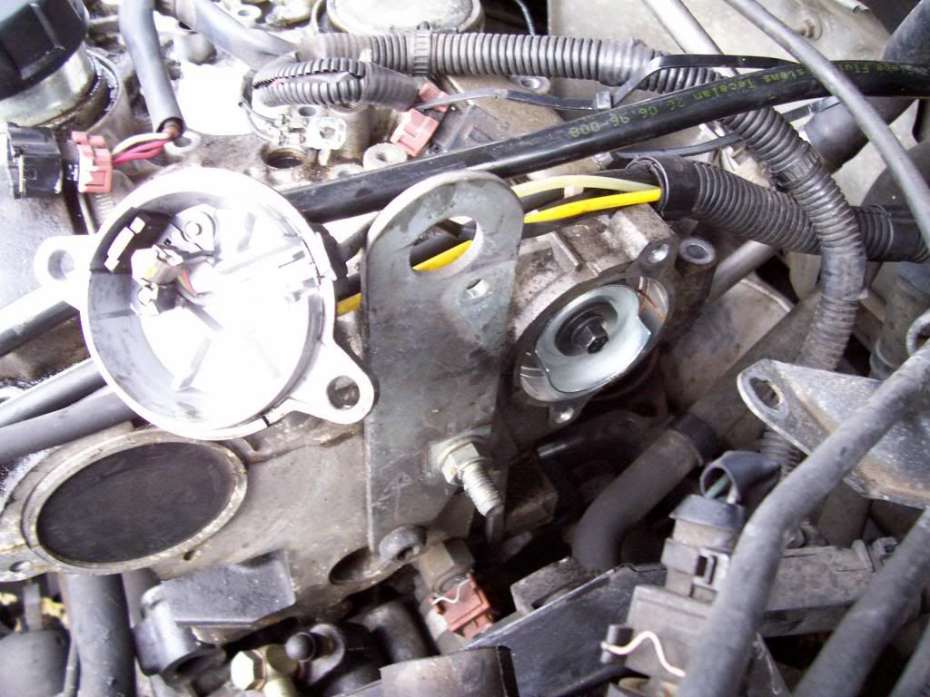 57. Undo and remove the 34 10mm bolts that hold the cam cover on. Work in a diagonal sequence from the outside towards the centre. 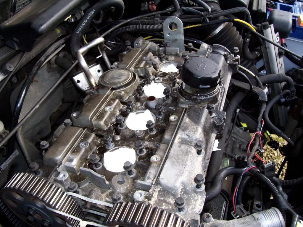 58. Tap the cam cover upwards with a rubber mallet to get it to come up and off. There are small protrusions on it that overhang the edges of the cylinder head for this purpose, though they don't give you an awful lot of room to swing and aim your mallet. You are now in the danger zone where you need to be very careful to protect the mating surfaces. So don't be tempted to shove anything like a screwdriver between cylinder head and cam cover to try to pry them apart. The cam cover is stuck down with a liquid gasket, and then when that breaks it may also be held quite firmly by the fact that that it is impaled on four metal dowels that poke out of the top of the cylinder head – three at the back, evenly spaced, and one in the middle at the front. The cam cover needs to come up exactly perpendicular to the cylinder head, or it will get jammed on the dowels. Possibly one side of the thing – front or back – will jump up a bit under the force of the valve springs, once the gasket seal is broken. If you bend down you should be able to see if one side is coming up more than the other, and apply your mallet appropriately. 59. When the camshaft cover is free, wrap your fingertips under the camshafts and carefully lift the cover and camshafts together clear of the head. Have a table or something ready so that you can put it down upside-down. 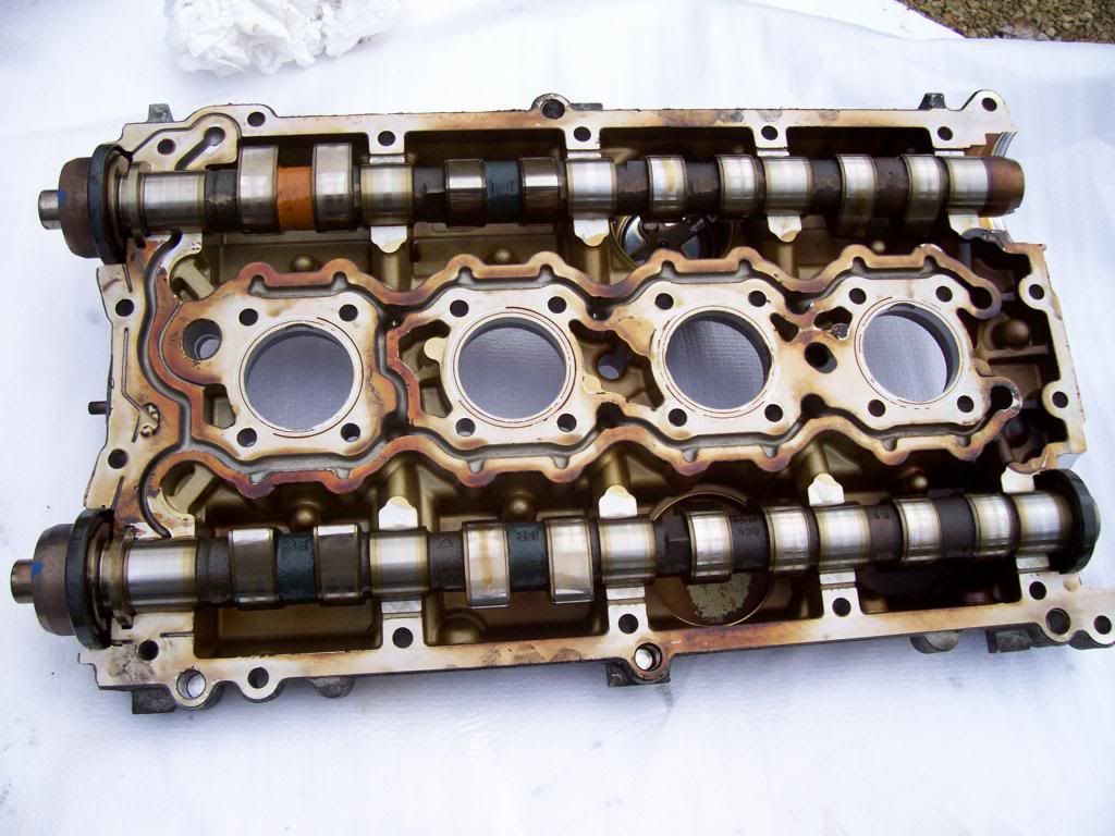 You will have now exposed the top of the cylinder head: 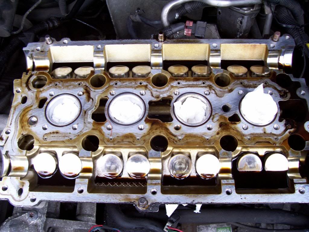 60. When you lift the cam cover, the sealing cap on the inboard side of the inlet camshaft will either come away with the cover, or be left behind in the cylinder head. Carefully remove it. Haynes says you can't re-use it; I say you can, at least if it is undamaged. Removing the head itself To remove the head itself you need first to release it from the engine mount on the right-hand side. So... 61. Support the right-hand side of the engine on a jack or similar. 62. Undo and remove the three 15mm bolts that go into a bracket on the right-hand side of the engine. 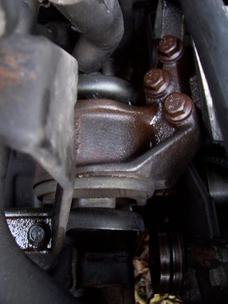 63. Undo and remove (18mm nut and bolt) the engine mount to the bodywork. The bolt is blocked by air conditioning pipes – you have to be fairly bold and brutal in forcing these out of the way. 64. Undo and remove the idler pulley for the auxiliary belt. Its bolt goes through a hole in the lower timing belt cover. 65. Pull up (and out) the lower timing belt cover. Clearance is limited, as with many things down this side of the engine, but it comes out if you shout at it a lot. 66. Undo the four bolts securing the mounting bracket to the side of the engine. With the bolts removed, it needs to be pulled off a dowel on the cylinder head, which is tight-fitting and difficult, before it can be removed. 67. There is a temperature sensor down on the bottom of the left-hand side (from the driver's perspective) of the cylinder head, in the centre of the car. Disconnect the wiring that goes to it (a simple electrical connector). 68. Undo the 10 long stretch bolts (14mm) that hold the head to the block. Work in pairs from the outside inwards, turning each of them just half a turn to start with: 3 7 9 5 1 4 8 10 6 2 Unless you are Superman you will need a longish bar as they are tight. Remove these bolts (you will need a pair of narrow pliers to grab their heads to lift them out of the recesses in the head). 69. Undo the two 10mm bolts holding a coolant pipe to the rear of the head on the right-hand side. 70. Lift up, and then ease the head towards the centre of the car (you need to lift it off pipes that protrude slightly from the engine block underneath, but then also to slide the dowel on the right-hand side of the head away out of the hole in the plastic timing belt guard). Again, have a table ready (suitably protected with an old sheet or something, if you are not binning the head, so that you can put it down quickly, as it is fairly heavy. 71. Lift off the old cylinder head gasket and discard. You have now worked your way down to the engine block. 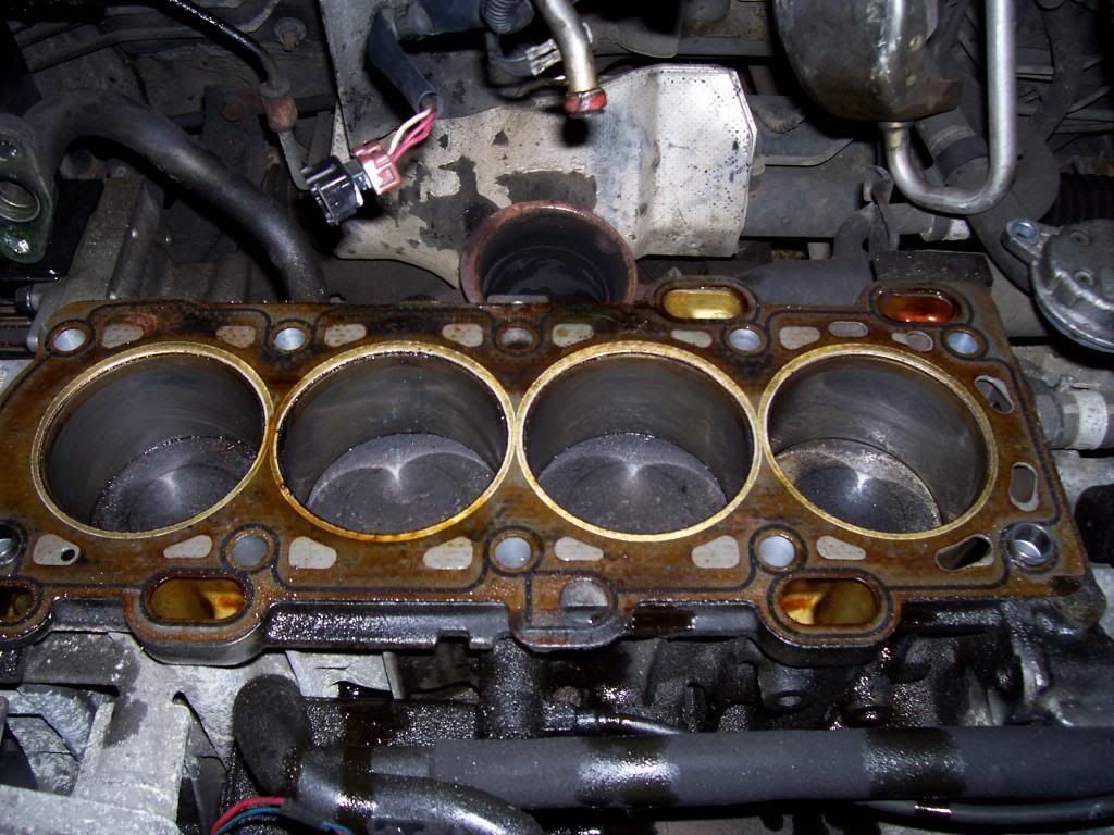 Rebuilding Head and camshafts 72. Remove the timing belt tensioner from the side of the engine, just above the crankshaft pulley (2 x 12mm bolts). (My car has the automatic timing belt tensioner. I gather that some have a manual one, for which you'll have to consult Haynes or another source as I have no experience of it.) 73. You need to compress the tensioner in a vice (or a G-clamp will do) before refitting. Compression has to be done slowly, over a period of about five minutes, so as not to damage the oil seals. You shove a narrow drill bit or similar through the holes to hold in in the compressed position when you have done it. 74. Thoroughly clean the mating surfaces of the block and the head. Use only gasket dissolver and soft scraper tools – not steel, which will mark the metal. 75. Install the new cylinder head gasket. 76. Carefully lower the new head on to the block. 77. Use new stretch bolts: tighten in three stages: 20Nm, 60Nm, then 130 degrees. Work out from the centre at each stage. 7 3 1 5 9 8 4 2 6 10 78. Attach the coolant pipe at rear of head. 2 x 10mm bolts. 79. Lubricate the camshafts and tappets with oil, as well as the shell bearings for the camshafts. 80. Replace the camshafts. There is no need, I think, to go through the Haynes rigmarole of putting them in the cam cover, and lowering it and them on to the head (having first made a tool out of welding rod to stop them falling off when you hold it upside down). I imagine that what they are trying to achieve, by this method, is to protect the cover, and especially the shell bearings for the camshafts in it, from being damaged as the carrier is bolted down – if you don't press it down straight, things can get slightly wedged/stuck and then suddenly jump/snap into place. So, instead, just do what the Vida instructions say and put the camshafts on the head and install the carrier/cover on top. The camshafts won't sit neatly until the cover is tightened down, because however you lay them, some of the cams will want to be exerting pressure on their valves, so the cover needs to be pressed down against the force of the relevant valve springs. Haynes (and Volvo) make a lot of fuss about putting the camshafts in the 'right' orientation. They go on about having the slot on the inboard end of the inlet camshaft above the centreline, and the slot on the exhaust camshaft below the centreline. This is sound advice if you are going to use the camshaft locking tool, but quite unnecessary if you are doing without it. All that really matters is that you don't mix up which camshaft is which. My inlet one had an orange-painted section on it, which is how I told it apart from the other. Obviously, also, it makes sense to lay the camshafts in an orientation such that you can see the paint marks that you are going to use when re-attaching the sprockets. So just put them back approximately as they were when you made those marks. They will then be in approximately the right orientation for when you fit the timing belt – which is when their being in the right positions becomes a critical matter. 81. Position new sealing rings for the spark plug wells in the circular spaces provided for them. 82. Apply the liquid gasket to the mating surfaces of the cam cover – I squeezed a thin bead along all the flat mating surfaces, and then spread it out thinly with a small foam roller. This seemed to work well. You must cover all the surfaces, but you need only the thinnest layer, and you need to be careful to keep the liquid gasket out of the oil channels. 83. Bolt down the camshaft cover (34 x 10mm bolts). Go steadily, work from the centre out towards the edges, a little at a time, so that you keep the cover/carrier level as you tighten it down – otherwise it will jam on the dowels that project up from the cylinder head. When it is finally bolted down on to the rest of the cylinder head, tighten the bolts to 17 Nm, again working systematically out from the centre to the edges. I managed without the special tool for pressing down the cover that fits where the spark plugs for cylinders 1 and 4 would normally go. (Haynes tells you how to build your own out of old spark plugs, nuts, bolts and strips of steel. It looks like a cool thing to make but I couldn't be bothered.) Possibly my method risks damaging the bolt threads, but I thought that with 34 bolts to share the load, if I turned each just a little at a time I would probably not be putting too much strain on anything. 84. Lubricate and drift in the camshaft oil seals, and replace the sealing cap on the inboard end of the inlet camshaft. Timing 85. Re-attach your camshaft sprockets to the camshafts, lining up your paint marks so that they are exactly as they were before you removed them. 3x 10mm bolts hold each one on; tighten to 20 Nm; to stop the camshafts turning, either build a counterhold tool as suggested in Haynes, or do what I did and jam an extension bar, wrapped in something soft, through one of the holes in the camshaft pulley so that movement is prevented by the fact that the bar can't get past the camshaft cover. 86. Get the timing marks on the camshaft sprockets so that they are roughly in the right positions. 87. Refit the timing belt tensioner – 12mm bolts; tighten to 25 Nm. 88. Remove the crankshaft auxiliary belt pulley, using the home-made counterhold tool described at the start. To do this, remove two of the four 10mm bolts and use them to attach the tool to the pulley; you can then use the home-made tool to hold the pulley still while you undo the central nut (30mm). Remove the tool and the remaining 10mm bolts and pull the pulley off its shaft (mine was difficult to remove – I had to lever it off with the handle of my breaker bar). 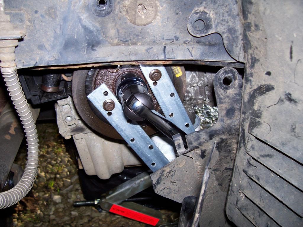 89. Re-fit the central nut on the crankshaft, with the pulley removed, so that you can use your 30mm socket to turn the engine. 90. Line up the timing marks at the crankshaft. Haynes has a decent illustration of these marks, whereas all my pictures were pretty useless: essentially there is a sort of distinctive hump at one point on the circumference of the thing that you can turn, which has to be lined up with a raised mark in the metal on the oil pump casing that lies behind it. You can just about see the set-up in the picture below, but as I say Haynes has a much better illustration. 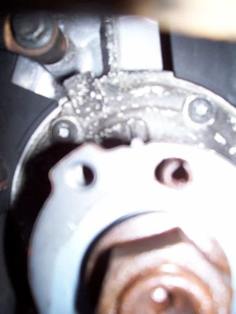 91. Temporarily re-fit the timing belt top cover, and line up the camshaft sprockets precisely with the timing marks on the timing belt top cover. As suggested earlier, you may need to wedge something like an extension bar or fat spanner into the holes in the sprockets to hold them in place, to stop them turning out of position under the force of the valve springs. 92. Fit the timing belt. Start at the crankshaft, and, keeping it taut, work up over the inlet and then the exhaust camshaft sprockets, then the water pump, and finish at the tensioner pulley. 93. Release the timing belt tensioner by pulling out the thing that you shoved in it after compressing it. Re-fit the little plastic horseshoe-shaped spacer at the top of the tensioner. 94. With the belt fitted, check and re-check all the timing marks. When you are satisfied, use the 30mm socket to turn the crankshaft two revolutions clockwise; check that all the marks end up where they started, and that there is no resistance as of pistons crashing into valves. Everything else 95. Re-fit the bracket to the side of the engine - 13mm bolts into the side of the cylinder head. Tighten in two stages: 35Nm and 75 degrees. 96. Re-fit the lower timing belt cover. Look at it carefully and you can see that it has little tabs that snap down into slots at the front and back of the bottom edge; also little tabs down the sides that clip over similar protrusions in the plastic on the edges of the inner cover that has stayed attached to the car throughout. 97. Re-fit the aux belt idler pulley that bolts through lower timing belt cover - 25Nm. 98. Re-fit the engine mount: Engine mount to engine bolts: two stages: 67Nm and 60 degrees. Engine mount to body: two stages: 50 Nm and 60 degrees. 99. Re-fit the crankshaft pulley: torque centre nut to 180 Nm (use your counterhold tool again); the four smaller 10mm bolts round the outside in two stages: 25Nm and then 30 degrees. 100. Re-fit the camshaft position sensor 10mm bolt – 17 Nm (the screws that hold the cover on only need 5 Nm) 101. Re-fit the inlet and exhaust manifolds. Tighten manifold bolts and nuts to 25Nm 102. Re-fit the heat shield that fits over the exhaust manifold. 103. Re-fit the downpipe to the exhaust manifold. 104. Re-fit the auxiliary belt, and all the fuel, ignition and throttle stuff, the radiator top and bottom hoses, and the electrical connectors that you disconnected earlier (throttle position sensor, idle control valve, and two temperature sensors – one on the head, one by the thermostat). Throttle housing bolts 10 Nm. 105. Check, check and check again that you have put everything back that you should have done, and that you haven't left any spanners etc where you didn't intend to. Further top tips from other members more experienced than me 106. Put a squirt of oil (a tablespoon or a bit more) into each cylinder before starting (squirt in via the spark plug holes), to lubricate and to improve compression on starting. 107. Don't be alarmed by the clouds of smoke that will come from the engine when you first start it. I understand that it is the oil and stuff from your filthy hands burning off all the bits that you have been handling. (It is very exciting. I wish I had made a video of it.) 108. Start first, and only then, if it's running OK, replace the coolant. This improves the prospects for diagnosing what is wrong if it doesn't all work smoothly.
__________________
(Formerly) 1988 745 B230K (Phoenix) Last edited by DWM; Dec 26th, 2013 at 23:23. |
|
|

|
| The Following 25 Users Say Thank You to DWM For This Useful Post: |
|
|
#2 |
|
Premier Member
Last Online: Nov 15th, 2022 21:34
Join Date: Apr 2010
Location: London / Essex
|
WOW!!! What can I say? Absolutely brilliant and many thanks for sharing it with us over here. Having guides like these, makes it a lot easier for people to understand what a head replacement involves.
Glad to see you remembered to include step 69......  . Completely forgot about the coolant hoses when I removed the head and struggled for a couple of minutes trying to figure out why the head would just not come out..... . Completely forgot about the coolant hoses when I removed the head and struggled for a couple of minutes trying to figure out why the head would just not come out..... And lastly, a quick question with regards to the zip ties experiment to see if it was securing the pulleys. Did it do the trick in your opinion? It is something I wanted to try, but haven't had the chance yet.
__________________
Current car: 2002 S40 1.9D, 1992 240SE Nullius in Verba
|
|
|

|
| The Following User Says Thank You to gatos For This Useful Post: |
|
|
#3 |
|
VOC Member
Last Online: Apr 4th, 2023 18:13
Join Date: Apr 2010
Location: Oxford
|
Many thanks. And thanks again for all your help.
Zip ties: Yes, I reckoned it would work. Apply too much turning force to the sprockets and yes, the ties broke; but I reckoned that if you were reasonably careful this would be a good simple method of keeping things in place.
__________________
(Formerly) 1988 745 B230K (Phoenix) |
|
|

|
| The Following User Says Thank You to DWM For This Useful Post: |
|
|
#4 |
|
Senior Member
Last Online: Aug 31st, 2015 03:01
Join Date: Apr 2007
Location: chesterfield
|
a VERY comprehensive guide to removing a cylinder head... it's always good to see pictures as well....
WELL DONE SIR...!!! however, I expect to see a "How To Replace a Cylinder Head".... and I expect it to be 5 times longer with 5 times as many pictures.... people do wonder why a garage charges £50+ and hour... 
__________________
 Current: 05 Mercedes C55 AMG, 97(R) V40 1.9 TD, 02(51) S40 S Past: 86(C) 360 GLT, 93(K) 940 Wentworth, 95(M) 440 Si, 94(L) 940 Wentworth, 91(J) 460 GLEi Auto, 98(R) S90 Executive II |
|
|

|
| The Following User Says Thank You to terrywilde07 For This Useful Post: |
|
|
#5 |
|
Master Member
Last Online: Aug 1st, 2023 20:43
Join Date: Feb 2012
Location: BATCAVE
|
Excellent guide DWM!

__________________
2003 V40 1.9 D SPORT 272K 2001 V40 T4 SPORT 134K ipse se nihil scire id unum sciat |
|
|

|
| The Following User Says Thank You to Cornishv40 For This Useful Post: |
|
|
#6 |
|
Premier Member
|
I can only echo what previous posters have said: that is a truly superb guide, and thank you!

__________________
1989 740 GL 2.0 estate 2000 V40 2.0 (gone) 2005 Toyota Avensis 2.0 estate (gone) 2012 Ford Mondeo 2.2 TDCi estate 1999 Land Rover Discovery 2 TD5 |
|
|

|
| The Following User Says Thank You to stephend For This Useful Post: |
|
|
#8 |
|
Premier Member
Last Online: Dec 28th, 2022 12:25
Join Date: Jun 2009
Location: Mercville
|
Simply Superb.........i think you really enjoyed your challenge!.......half the battle is having another motor you can use so no hurry needed, you can just take your time.
When i used to strip engines my mates used to come around and secretly drop a few washers and nuts in my parts box....at first i used to worry about bits left over but i always found another place for them and used them all up! Keith
__________________
 Mercedes C320CDI Sport Estate 3 litre V6 7 Gear Auto Remap 290bhp 628Nm torque @ 1600revs 45.1mpg |
|
|

|
|
|
#9 | |
|
Premier Member
|
Quote:

__________________
1989 740 GL 2.0 estate 2000 V40 2.0 (gone) 2005 Toyota Avensis 2.0 estate (gone) 2012 Ford Mondeo 2.2 TDCi estate 1999 Land Rover Discovery 2 TD5 |
|
|
|

|
| The Following User Says Thank You to stephend For This Useful Post: |
|
|
#10 | |
|
VOC Member
Last Online: Apr 4th, 2023 18:13
Join Date: Apr 2010
Location: Oxford
|
Thank you very much, and thanks again for all your help.
Quote:
 . I'm very lucky. I hate to think what I would have done without the extra one. I'd certainly have had to scrap the V40... . I'm very lucky. I hate to think what I would have done without the extra one. I'd certainly have had to scrap the V40... And yes I did enjoy it... except when I was freezing, filthy, and losing quantities of flesh off the backs of my hands in a battle with some inaccessible part... i.e. 90% of the time... 
__________________
(Formerly) 1988 745 B230K (Phoenix) |
|
|
|

|
| The Following User Says Thank You to DWM For This Useful Post: |
 |
| Currently Active Users Viewing This Thread: 1 (0 members and 1 guests) | |
|
|