
|
|||||||
| PV, 120 (Amazon), 1800 General Forum for the Volvo PV, 120 and 1800 cars |
 Information
|
|
1961 Volvo PV544 in HollandViews : 88697 Replies : 750Users Viewing This Thread : |
 |
|
|
Thread Tools | Display Modes |
 Mar 10th, 2019, 14:39
|
#631 |
|
Premier Member

Last Online: Yesterday 15:30
Join Date: Jul 2007
Location: Connecticut, USA
|
Army;
I guess my posting was somewhat simplified...those open, two crimp area terminals you show are also good, industrial quality, and similar to what Volvo used on the Amazon Headlight (and others) Hex connector (See: http://www.sw-em.com/voltage_drop_in..._connector.htm ), but they must be used in conjunction with the very specific crimping tool, which crimps both conductor and insulation as a strain relief. For instance, in the avionics industry, jaws of that tool would have been specified for gauge of the conductor, and material and OD of the insulation, and the tool would have a mechanical provision to assure crimp was completed and not stopped before it was completed to the end of excursion (I call that non crimpus abortus!), and the excursion was also limited to prevent overcrimping, in order for everything to be perfect...those tools cost hundreds of $... Conductor area of crimp should look like this in cross-section (and idealy, per my recommendation, with what minuscule air air-space is left, taken up by ACZP!): 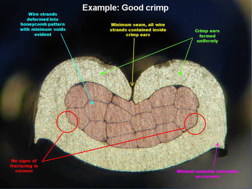 ...not like this: 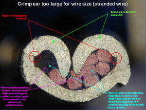 Source: https://www.etco.com/engineering-guides/ Regarding that manual crimper Derek links...it looks to be a single dimple type which also looks like it should work well...I would recommend using it in a vice or arbor press or set it up hydraulically in order to have a high degree of control over the amount and excursion of force. Once again, the point is made that with crimping, although a very simple operation, a lot can go wrong, so operator care, proper use of tools and inspection after the operation to assure finished product, are all quite important. Cheers Last edited by Ron Kwas; Mar 10th, 2019 at 14:41. |

|

|
| The Following 2 Users Say Thank You to Ron Kwas For This Useful Post: |
|
Mar 10th, 2019, 19:33
|
#632 |
|
marches on his stomach
Last Online: Feb 11th, 2022 03:15
Join Date: Jan 2018
Location: Somewhere in the Netherlands
|
Thanks for adding that Ron - it is a bit of a learning curve for me at the moment.
__________________
1961 Volvo PV544 the quick and easy in between project(!) 1981 Mercedes 300D <=> 230 diesel to petrol conversion project 1965 Series 2a Station Wagon mega build 1992 Mercedes 190E The car that works! 
|
|
|
|
|
Mar 10th, 2019, 19:48
|
#633 |
|
marches on his stomach
Last Online: Feb 11th, 2022 03:15
Join Date: Jan 2018
Location: Somewhere in the Netherlands
|
I thought I'd show what's been taking me so long to get what feels like almost nowhere.
Being of the non electrical type it has taken me a fair amount of puzzling and faffing about trying to get some sort of a plan formulated. Here's what has evolved so far => The explanation is as follows Part A - a big old terminal and distribution thing - is used for the "always live" parts such as the interior light, the horn and side / parking lights. From this two chunky 6mm^2 cables run down to two 40 Amp in-line fuses that protect two 40 Amp relays (Part C for example) that will be activated by the ignition switch. In this way only a small current will be passed through the ignition switch - the hard work will go through the relays. Each relay has its own "big old terminal and distribution thing" - Part D and Part E The light green wires running from Part E power the lower row of fuses (Part F) - whilst the purple wires power the upper fuse row. That simple colour coding helps me trace things slightly more quickly. The smaller size relays with a "D" for diode on them (the bigger relays are also diode versions used to try and aid electronics I might be running from the power sockets) that sit between the big relays and the fuse box are all rated at 20 Amps (if I remember correctly) and are used for things such as fog lights and horns and headlights and the blower motor etc I need to group the switching sides of the relays into connectors that will all come from a common feed from the corresponding parts D, E, and A. These wires will be detachable from a new loom section - much like the other connectors that go to the loom sections I've already fitted - so I can remove and change / repair this whole fuse box and relay section away from the rest of the wiring in the car.
__________________
1961 Volvo PV544 the quick and easy in between project(!) 1981 Mercedes 300D <=> 230 diesel to petrol conversion project 1965 Series 2a Station Wagon mega build 1992 Mercedes 190E The car that works!
Last edited by Army; Mar 10th, 2019 at 19:51. |
|
|
|
|
Mar 11th, 2019, 14:16
|
#634 |
|
VOC Member

Last Online: Jun 22nd, 2024 14:01
Join Date: Jul 2006
Location: Chatham
|
Total overkill but looks great!

|
|
|
|
|
Mar 11th, 2019, 16:23
|
#635 |
|
Master Member
Last Online: Today 02:40
Join Date: May 2017
Location: New Milford, Connecticut
|
 ") Next time I visit, I won't be surprised if you're connecting it all to an ECU and adding an OBD II port. I can't estimate the size. Where will this be mounted? Also what are those red circular "terminal blocks" called (A, B, C & D) and what was your source for them? |
|
|
|
|
Mar 11th, 2019, 21:13
|
#636 | ||
|
marches on his stomach
Last Online: Feb 11th, 2022 03:15
Join Date: Jan 2018
Location: Somewhere in the Netherlands
|
Quote:
As far as I am concerned OTT is the only way to go... Quote:
I'll try to do a trial fit picture tomorrow. ##### The terminal posts were bought here => LINK REMOVED! www.rdae.nl I can't remember the maker's name of the posts - there's a bit of English description in the link given (under the Dutch information) I'll try to remember to find the packaging tomorrow to see if I can find the manufacturer for you. They are nice good quality posts - kinda handy if you like OTT(!) ##### I am actually considering a OBDII port and such silliness - I have an idea that I might be able to rip out the electrickery from say a cheap Volvo V40 and bung it on a B20. This would work out to be cheaper than fitting a tunable Megasquirt system... ...at least I have the electrical power circuit ready for such an upgrade (as well as the many other upgrades I might want to make such as heated rear windscreen, electric fuel pump, blah blah blah - the wires are {almost} already there)
__________________
1961 Volvo PV544 the quick and easy in between project(!) 1981 Mercedes 300D <=> 230 diesel to petrol conversion project 1965 Series 2a Station Wagon mega build 1992 Mercedes 190E The car that works!
Last edited by Army; Mar 11th, 2019 at 21:31. Reason: Following advice |
||
|
|
|
|
Mar 11th, 2019, 21:27
|
#637 |
|
Master Member
Last Online: Today 02:40
Join Date: May 2017
Location: New Milford, Connecticut
|
OK. Rick Donkers Auto Electrics is where you got them.
But pull down the link because I think it has your email and password autosaved on that linked page. |
|
|
|
|
Mar 11th, 2019, 21:33
|
#638 | |
|
marches on his stomach
Last Online: Feb 11th, 2022 03:15
Join Date: Jan 2018
Location: Somewhere in the Netherlands
|
Quote:
Link removed just to be sure - I don't think my email or password is autosaved on that page - but I would appreciate you sending me a PM with that information so I can see if it is the case (!) Scary interweb...
__________________
1961 Volvo PV544 the quick and easy in between project(!) 1981 Mercedes 300D <=> 230 diesel to petrol conversion project 1965 Series 2a Station Wagon mega build 1992 Mercedes 190E The car that works!
|
|
|
|
|
|
Mar 11th, 2019, 22:35
|
#639 |
|
Master Member
Last Online: Today 02:40
Join Date: May 2017
Location: New Milford, Connecticut
|
PM sent, but never mind. I spoke too soon. The link does not connect to your account.
|
|
|
|
|
Mar 12th, 2019, 12:34
|
#640 |
|
marches on his stomach
Last Online: Feb 11th, 2022 03:15
Join Date: Jan 2018
Location: Somewhere in the Netherlands
|
...as usual the fuse box and wiring arrangements ended up needing a bit more space than I had planned. I'm glad I went for the mini fuse box and the smaller relays - they have saved space (for all of the Gucci round buzz bar type things)
The tray size is 27 cm long and 25 cm wide - I could have cut it down to be smaller but I will probably add on the resistor for the electronic ignition and the resistor for the half power demister fan too - and you never know there could be another addition (!) Here's a dodgy picture of the "mother ship" in the place where I want to fit it => It is kind of in the upper right hand corner of the foot well - this part is curved on the edges so I designed the sides on the tray to be slightly forward of the central piece. Here's another dodgy shot through the hole for the glove compartment => I think there's just enough room to shove the tray / board as high as possible and still be able to remove the fuse box cover with out having to remove the glove box inner box. (This is a bit more important in my case because the glove box inner box was one of the many upgrades that came with the car - it has been re-manufactured in metal - the original ones are cardboard I think) If I need a bit more room there's just about enough space to lower the tray with out it becoming a kick hazard (for a nervous passenger - you know the type - the type of passenger who "brakes" when they think you should!)
__________________
1961 Volvo PV544 the quick and easy in between project(!) 1981 Mercedes 300D <=> 230 diesel to petrol conversion project 1965 Series 2a Station Wagon mega build 1992 Mercedes 190E The car that works!
|
|
|
|
|
| Currently Active Users Viewing This Thread: 1 (0 members and 1 guests) | |
|
|


 Linear Mode

