
|
|||||||
 Information
|
|
Boost GaugeViews : 5757 Replies : 70Users Viewing This Thread : |
 |
|
|
Thread Tools | Display Modes |
 May 16th, 2010, 12:06
|
#41 |
|
Premier Member

Last Online: May 22nd, 2024 11:32
Join Date: Oct 2008
Location: Cranfield
|
Ah sorry, I must have gave the wrong impression, it's not for sale. I was just showing you what you could do.
You have a pm 
|

|

|
|
May 19th, 2010, 04:39
|
#42 |
|
I've Been Banned
Last Online: Jun 15th, 2015 21:48
Join Date: May 2009
Location: BURGESS HILL
|
I thought I had it all sewn up in my mind,that a new pipe feeds from the turbo to the mbc,and out the other side of the mbc to the wastegate actuator,using the supplied T piece in between for the hose to the gauge but thats clearly not the case.
Help please if you can... Shaun |
|
|
|
|
May 19th, 2010, 10:13
|
#43 |
|
VOC Member

|
Throw the T piece away.
For the mbc, turbo>mbc>actuator. For the boost gauge you need a 1/8" BSP nipple to connect the gauge line onto the inlet manifold.
__________________
Gavin  1997 945 CD (B230FK) [RIP: 1991 945 Turbo (B230FT) 1992 945 SE turbo (B200FT)] |
|
|
|
|
May 19th, 2010, 12:02
|
#44 |
|
I've Been Banned
Last Online: Jun 15th, 2015 21:48
Join Date: May 2009
Location: BURGESS HILL
|
I dont understand why I have to throw away the t piece, and go out and buy another one??
|
|
|
|
|
May 19th, 2010, 13:27
|
#45 |
|
Premier Member
Last Online: May 22nd, 2024 11:32
Join Date: Oct 2008
Location: Cranfield
|
You don't need the T piece.
Here's a quick diagram I drew while having lunch, sorry you'll have to crank your neck a bit... 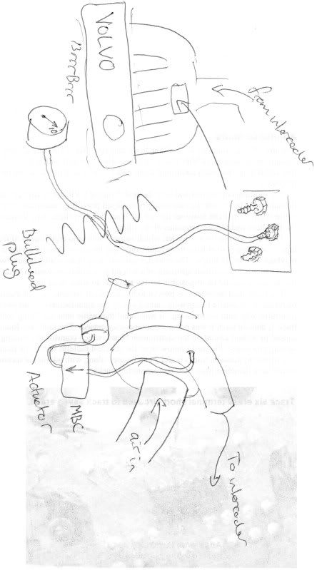 If you look at the top of the picture, you can see my fine drawing of a volvo engine. You can see that I've drawn the intake manifold too. You can see that I've highlighted a rectangle on it. This is where all the vacuum hoses go to. On a HPT model, this is where the boost gauge gets it's pressure reading from. This is where you need to take one of of the vacuum hose and connect it up as GPL said with a BSP fitting (try machine mart) using one of the blanked off holes. On my car there are three vacuum hoses coming from here, the middle one is the one used for the gauge. Then just run the hose into the car, being careful not to run it anywhere where it could be pinched. Mine runs along with the wiring loom, held in loosely by the replaceable cable ties along the rear of the engine compartment. The lower bit of the diagram shows the turbo. It's really simple, remove the end of the existing hose which goes to the compressor housing. If the hose looks good and isn't damaged, leave the other end attached to the actuator. This becomes one of your new hoses. Before you connect your MBC, blow through it and set the dial so that the air can flow through freely, but if you turn it further, it begins to get restrictive. This will save you a load of time trying to find the 'sweet spot' when you're setting it up on the road. Connect the outlet port of your MBC to the hose going down to the actuator. Now using your fresh vacuum hose, cut a piece just long enough to connect the inlet port of the MBC to the outlet port on the compressor housing. Make sure there are no nips or tight bends in any of the hoses. Be certain to secure all the hoses with cable ties or the original clips. Once you've done all that, don't drive it yet. You've just added a device that is very capable of sending connecting rods through the side of your engine block. Report back and we'll tell you how to set it up on the road, because this is one thing you don't want to get wrong, especially on a nice 1998 car 
|
|
|
|
|
May 19th, 2010, 13:31
|
#46 |
|
Premier Member
Last Online: May 22nd, 2024 11:32
Join Date: Oct 2008
Location: Cranfield
|
The reason you don't need the T piece, is because it's better to have an unrestricted primary pressure tapping than a secondary one that has been spliced into another system, which could give you errors in your pressure reading.
The reason you don't want to connect your gauge to the MBC hose is that this isn't the pressure entering your engine. The pressure at the intake is likely to differ from that immediately after the turbo. |
|
|
|
|
May 19th, 2010, 16:07
|
#47 |
|
Junior Member
Last Online: Apr 6th, 2011 16:59
Join Date: Sep 2007
Location: ipswich
|
mmm very interesting , i now know who to ask when i do mine lol
|
|
|
|
|
May 19th, 2010, 16:41
|
#48 |
|
I've Been Banned
Last Online: Jun 15th, 2015 21:48
Join Date: May 2009
Location: BURGESS HILL
|
Chris, thats very,very helpful.
Actually, I was quite close to whats required., except for the gauge connection. Only one more query before I investigate further and that refers to the"pressure relief valve" that Ive read about,either from the MBC or a special Tee piece.The red mbc I bought does not seem to have the hole anywhere.What do you suggest for this. I wont throw the Tee piece away that was sent because it might come in useful for something..... There appears to be a vacuum hose from the inlet manifold which goes into the cabin in the centre, but to the left of the clutch pedal. Could that be pre fitted for a non existent gauge? Its also very easy to confuse INLET with INTAKE,until I am familiar with each one. I wont throw the Tee piece away that was sent because it might come in useful for something..... Last edited by Profpriv; May 19th, 2010 at 16:57. |
|
|
|
|
May 19th, 2010, 16:59
|
#49 |
|
Premier Member
Last Online: May 22nd, 2024 11:32
Join Date: Oct 2008
Location: Cranfield
|
The MBC doesn't 'vent' any air. It works by restricting the flow. When the pressure builds up to the desired pressure, it lets it past. A bit like blowing the cork out of a bottle of champagne lol
|
|
|
|
|
May 19th, 2010, 17:03
|
#50 |
|
Premier Member
Last Online: May 22nd, 2024 11:32
Join Date: Oct 2008
Location: Cranfield
|
That'll probably go to the ECU. I don't see why you couldn't 'T' into that line. Check first though, I'm not 100%.
|
|
|
|
|
| Currently Active Users Viewing This Thread: 1 (0 members and 1 guests) | |
|
|


 Linear Mode

