
|
|||||||
| LPG, CNG & LNG - General Info and Issues Share experiences and problems |
 Information
|
|
Phase 2 V70 T5 LPG Guide (and questions)Views : 5804 Replies : 16Users Viewing This Thread : |
 |
|
|
Thread Tools | Display Modes |
 Apr 13th, 2011, 20:33
|
#11 |
|
Senior Member
Last Online: Jan 11th, 2013 22:01
Join Date: Dec 2008
Location: Cardiff
|
so I fitted the vaporiser, you need to remove the airbox and use a bracket coming off the front of the plate that is removable.
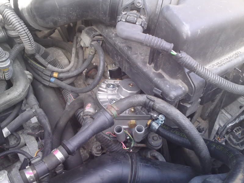 I have plumbed all of the coolant hoses up, will post pics later on once all collated. Dai, what I need to know is there is only one existing factory vacuum outlet on the inlet manifold as below: 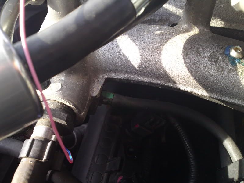 Why can I not T into this as close to the manifold as possible? Surely vacuum is vacuum throughout the manifold and that pipe? It's not like I'm T'ing into a brake servo? I never had had the nipple you speak of so would only be able to use one of the injector nozzle ones that is spare should I drill a new hole? I'm a bit stumped as to the physics why I cannot T off that tube? |

|

|
|
Apr 13th, 2011, 23:43
|
#12 |
|
Trader Volvo in my veins

Last Online: Yesterday 21:49
Join Date: Dec 2004
Location: Anglesey
|
The vacuum needs to be a dedicated point as the reading will control the fuel pressure and is used for the mapping of the system.
Many vacuum pipes already fitted to the car can be connected to solenoids that open and closes changed the amount of vacuum. If you can be 100% sure there is no solenoid in the line then it is ok to T into the line. Provided that the vacuum pipe will fit of the injector nossel it will do perfectly fine for the purpose. T'ing into an existing line is common trade error causing intermitant poor running and many installers can not see the error in their ways with it. |
|
|
|
|
Apr 15th, 2011, 00:35
|
#13 |
|
Senior Member
Last Online: Jan 11th, 2013 22:01
Join Date: Dec 2008
Location: Cardiff
|
Dai did you get my text?
|
|
|
|
|
Apr 16th, 2011, 22:09
|
#14 |
|
Trader Volvo in my veins
Last Online: Yesterday 21:49
Join Date: Dec 2004
Location: Anglesey
|
text replied. Cheers
|
|
|
|
|
Apr 16th, 2011, 22:16
|
#15 |
|
Senior Member
Last Online: Jan 11th, 2013 22:01
Join Date: Dec 2008
Location: Cardiff
|
Dai, in order to locate the tank as far to the right of the boot as possible I will need to cut out a section of the metal. Did you just use a disc cutter for this?
|
|
|
|
|
Apr 17th, 2011, 19:38
|
#16 |
|
Trader Volvo in my veins
Last Online: Yesterday 21:49
Join Date: Dec 2004
Location: Anglesey
|
No need for any cutting. Just mount the tank centraly in the wheel well.
|
|
|
|
|
Apr 17th, 2011, 20:46
|
#17 |
|
Senior Member
Last Online: Jan 11th, 2013 22:01
Join Date: Dec 2008
Location: Cardiff
|
Dai, I had to cut some of the metal at the top end as without doing so the multivalve outlets would not have fitted below.
A few questions following our earlier conversation: 1. With respect to the bumper bracket mount, will the filling point be hidden behind the tow eye cover or will it be below the bumper completely? If the latter, what is the minimum height from the floor? 2. What is the best way to route the LPG switch into the interior? 3. With the copper piping, how much of the rubber/plastic covering should be removed to fit it correctly into each compression joint? 4. Can you email the best wiring diagram you have please? 5. What size bolts go into the tank? The ones supplied were too small Thanks Last edited by Gareth83; Apr 17th, 2011 at 21:00. |
|
|
|
|
| Currently Active Users Viewing This Thread: 1 (0 members and 1 guests) | |
|
|


 Linear Mode

